AR1 · DC Circuits · Final Project
Design &
Design &
Simulation
MCQ · Quick Check
Quick check.
Question 1
Which function models the HIGH and LOW times in our circuit?
- A t = I·R
- B t = 0.693·R·C
- C t = V/R
- D t = P·t
Question 2
In our circuit, t1 depends on: (select all that apply)
- AR1
- BR2
- CC
- DAll
Question 3
In our circuit, t2 depends on: (select all that apply)
- AR1
- BR2
- CC
- DAll
Before You Build
Check your design.
Confirm that your circuit meets each requirement before you pick up a component.
- Your circuit switches between two values of R1 to produce two different pulse widths.
- R2 stays the same, so the low time remains constant.
- C stays the same, so the total period stays consistent.
My Design
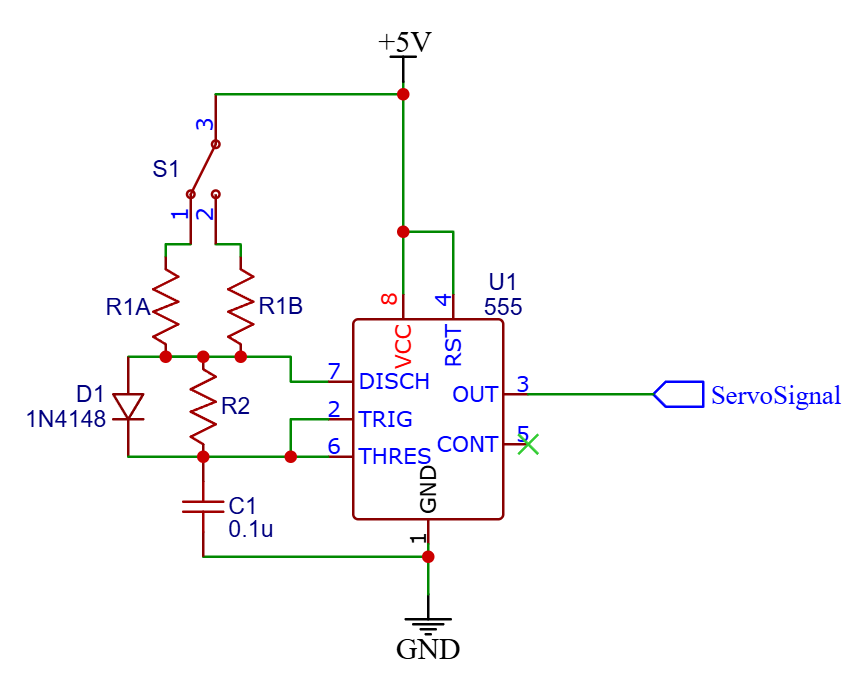
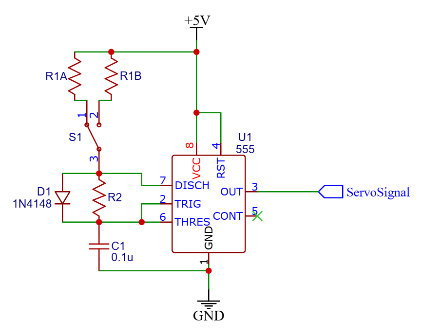
Here are two approaches that work.
Version 1
Version 2
How do we know either approach works before building it?
The Problem with Skipping Ahead
Jumping straight to building creates avoidable problems.
- You may spend several class periods rebuilding a circuit that was never verified to work as designed.
- Without a known-good signal to compare against, debugging becomes guesswork: every symptom looks like every other symptom.
- Some faults stay completely hidden until you actually measure the output with an oscilloscope.
What Simulation Does
Simulation answers the important questions before you build.
- Test whether your timing formula gives the pulse widths you calculated, with no components required.
- See the output signal on a virtual oscilloscope and verify it matches your design.
- Catch and fix mistakes in seconds rather than rebuilding on a breadboard.
Use simulation to verify your design works before you build.
The goal is to confirm, not to guess. Simulation is the check before the build, not a shortcut around it.
Getting Started
Open Tinkercad.
- Google Classroom: open the Tinkercad simulation assignment in your class stream.
- Sign in: use your .gse account when Tinkercad prompts you to log in.
Live Demo
Follow along.
1
Power first: place and configure the power supply before adding any other components.
2
Measurement tools matter: add an oscilloscope so you can see what the circuit is actually doing.
3
Add the 555: place the 555 timer IC and connect it to the power rails.
4
Add the diode: the line on the diode matches the line on the schematic.
5
Prep for servo: Make a place for the servo to connect.
Your Turn
What you will build in Tinkercad.
In Tinkercad
- A 555 timer circuit with your calculated component values.
- Two values of R1, switchable with a button.
- One R2 and one capacitor C that stay fixed.
- A servo connected to the 555 output pin.
What to Look For
- Does the output signal change when you press the switch?
- Does the pulse width match your timing formula calculations?
- Does the servo move between the two positions you designed for?