AR1  ·  DC Circuits  ·  Final Project Kickoff

Signals &
Motion

FRQ  ·  Motor Design Recall

What features make a motor "good" for a task?

What would make you choose one motor over another?
Design Requirements

Motors are classified by:

  • Speed: how fast the shaft rotates
  • Torque: how much force it can apply
  • Control: how easy it is to start, stop, and direct
  • Precision: how accurately it reaches a target
Which motor is best if you need:
  • Precise position
  • Repeatable movement
  • Simple control, no complex programming
The Answer

Servo Motor

// Precise position  ·  Simple signal control  ·  Built-in feedback

Servo Motor

What is a Servo?

A servo motor combines a simple DC motor with a position sensor and a control circuit that work together to reach and hold a specific angle.

  • It moves to a position when it receives a command signal.
  • It holds that position with force, even if something pushes against it.
  • It does not spin continuously like a DC motor. It rotates to an angle and stops.
  • It often has a built-in gear train for increased torque.
Control Signals

What controls the servo?

A DC motor is simply turned on and off. When power is applied it spins; when power is removed it stops.

A servo motor is always powered. Power keeps it energized and able to hold position at all times.

A special repeating signal tells the servo exactly which position to move to. The signal, not the power, controls the angle.
Pulse Width → Position

Pulse Width Controls Position


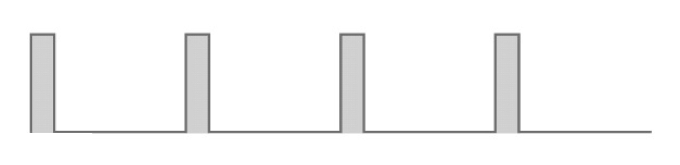
The signal repeats about every 20 ms. The length of the HIGH pulse in each cycle tells the servo where to go.

~1 ms pulseShort HIGH time
Short pulse, servo at 0 degrees
~1.5 ms pulseMedium HIGH time
Medium pulse, servo at 90 degrees
90°
~2 ms pulseLong HIGH time
Long pulse, servo at 180 degrees
180°
Live Demo

Let’s see how
pulse width
controls position.

// Watch what happens when the button is pressed and released.

FRQ  ·  Observation

What did you notice?

Describe what you observed when the button was pressed and when it was released. Be as specific as you can about what the servo did.
Observation Focus

What the signal looked like:

Button Released
Short pulse, servo at 0 degrees
Pulse Width
~1 ms
Servo Position
~0°
Button Pressed
Long pulse, servo at 180 degrees
Pulse Width
~2 ms
Servo Position
~180°
Changing the pulse width by just 1 ms swings the servo arm from one extreme to the other.
MCQ  ·  Design Connection

What are we controlling?

  • A Speed
  • B Position
  • C Power
Project Goal

New problem to solve.

Now that we know what a servo needs, let’s define what our project must do.

  • 01Create two distinct positions for the servo arm.
  • 02Control those positions with a circuit we design, not pre-written code.
  • 03Switch between positions using only analog components, not a microcontroller.
Making the Signal

What tool do we already have?

To drive a servo, we need a circuit that creates a repeating signal: it pulses HIGH and LOW over and over, and the length of each HIGH pulse controls position.

Have we seen anything like that? Think back to the start of this unit. We built a circuit that turned something on and off repeatedly at a controlled rate.
The Tool

555 Timer

We used the 555 timer to make lights flash at the start of this unit. That circuit simply turned a load on and off, over and over, at a rate set by resistors and a capacitor.

If we speed up the timing and control the pulse length carefully, that same circuit can generate the signal a servo needs.
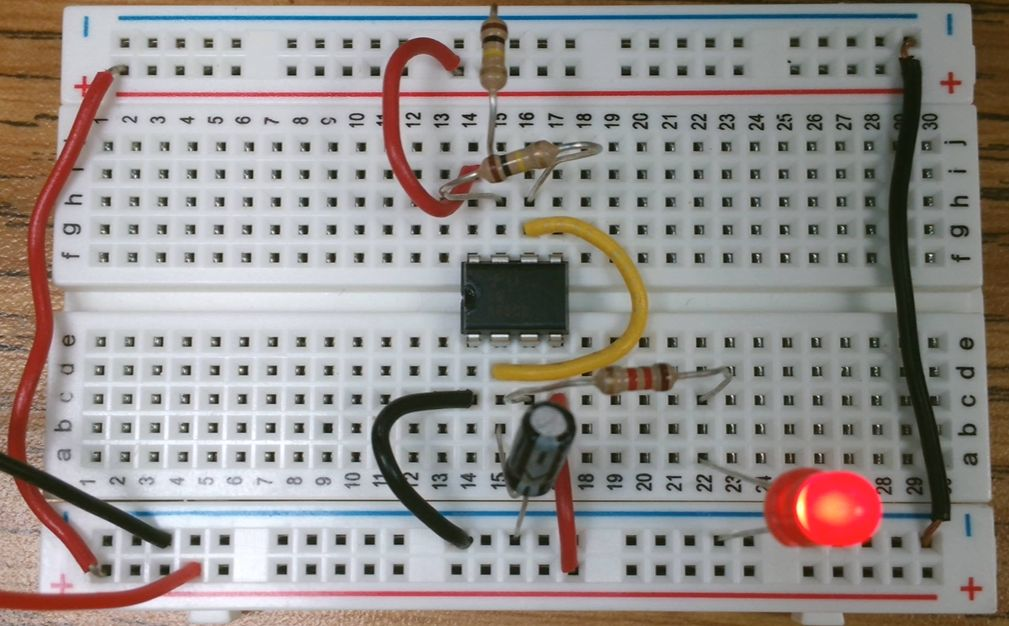
Different timing values will allow us to use the same chip to control the servo position. The servo signal is just a very fast, precisely timed version of the flasher.
555 timer flasher circuit on breadboard
Controlling the Timing

What controls the timing?

Look at this version of the 555 circuit. I've added a diode D1 which separates the charge path from the discharge path. Adding the diode allows R1 to control the HIGH time and R2 to control1 the LOW time independently.
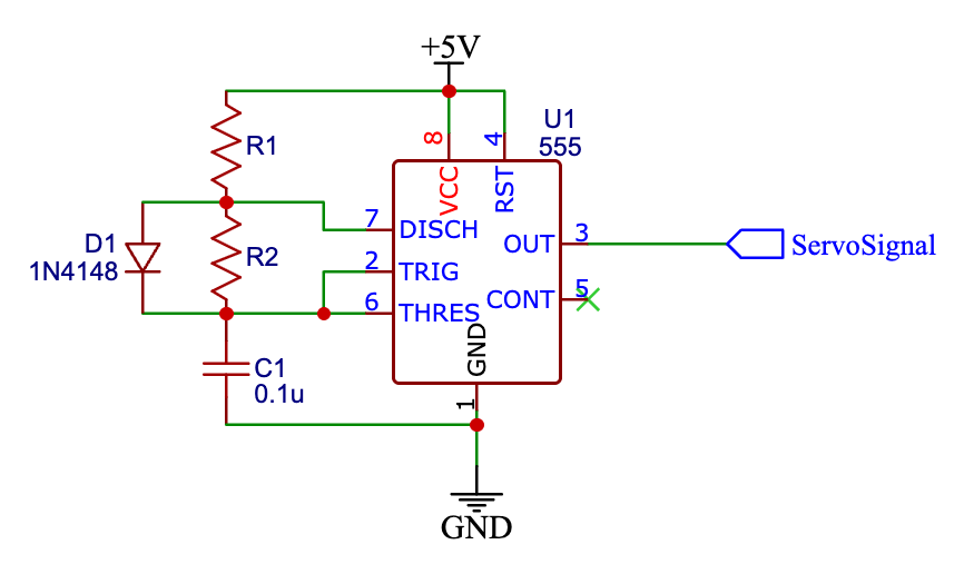
This separation is important. For a servo, we need precise control over the HIGH pulse without affecting how often the signal repeats.
555 timer circuit with diode separating R1 and R2 paths
555 Timer Timing

The control signal has two parts.

Every cycle of the 555 timer output consists of a HIGH phase and a LOW phase. Together they define how fast and how long the signal pulses.

Pulse train showing high time t1, low time t2, and one full period
t1
t2
period
t1=HIGH time: the pulse the servo reads
t2=LOW time: the gap between pulses
Period = t1 + t2

How often the signal repeats. For a servo this should be about 20 ms.

Timing Formulas

Calculating the timing.

Symbol Formula Controls
t1 0.693 × R1 × C Servo position: the HIGH pulse width
t2 0.693 × R2 × C LOW time separating each pulse
Period t1 + t2 How often the signal repeats (~20 ms total)
If R1 increases, the capacitor charges more slowly. What happens to the pulse width?
If R2 decreases, the capacitor discharges faster. What happens to the signal period?
The Design Problem

Two positions need two pulse widths.

Changing the pulse width means changing the charging resistor R1. A larger R1 slows the capacitor charge, making a longer pulse. A smaller R1 allows faster charging, making a shorter pulse.

Design question: How can we change the value of R1 while the circuit is running, without stopping the signal?
Think about components we have used. Is there something that can take a resistor in or out of a circuit using only a simple manual action?
Design Challenge

Design your circuit.

Here is a basic 555 timing circuit. Use it as your starting point.

555 timer circuit with diode separating R1 and R2 paths

Draw a version of the circuit that allows you to quickly switch between two different values of R1.

Your circuit should produce two different pulse widths and move the servo to two distinct positions.

Label R1A and R1B for each position.

Show how the switch connects them. Identify which resistor creates the longer pulse and which creates the shorter pulse.

Final Project

Your Project.

Build a VEX machine that does something useful using the circuit you just designed.

  • 01Use one servo as the actuator that does the work.
  • 02Build one control circuit using a 555 timer that creates two distinct pulse widths.
  • 03Use resistance to control timing: no microcontrollers, no code.
  • 04The machine should do something useful: a gate, a sorter, a clamp, a signal arm, or your own idea.