Soldering &
Measuring Resistance
Through-Hole Soldering & Multimeter Skills
What is Soldering?
- Soldering is one of the most fundamental skills in electronics. The two go together like peas and carrots.
- A whole new world opens up once you can pick up a soldering iron: you can build, repair, and customize electronic circuits at the component level.
- In this lab we cover through-hole (PTH) soldering: components go through holes in the PCB and are soldered on the back side.
- We will solder 10 resistors to a Resistor Check PCB, then measure each one with a multimeter and record the results.
 Today's project: Resistor Check PCB
What is Solder?
// Solder — the noun
An alloy of two or more metals, sold as thin wire on spools or tubes. Available leaded and lead-free.
// Solder — the verb
To join two pieces of metal at a solder joint. "We solder with solder!"
// Leaded (Pb + Sn)
Lower melting point, excellent flow. Still preferred by many hobbyists — handle with care.
// Lead-Free (RoHS)
Higher melting point, uses a flux core to aid flow. Industry standard for commercial products.
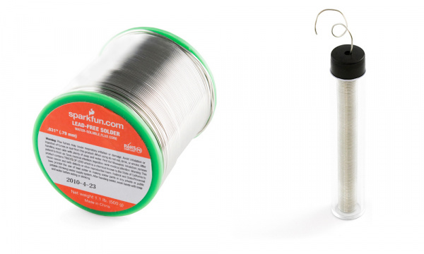 Spool (left) & tube (right) — leaded and lead-free varieties
Soldering Iron — Types
// Simple Wand Iron
Plugs directly into the wall. No temperature control — the heating element is built into the wand. Affordable and portable.
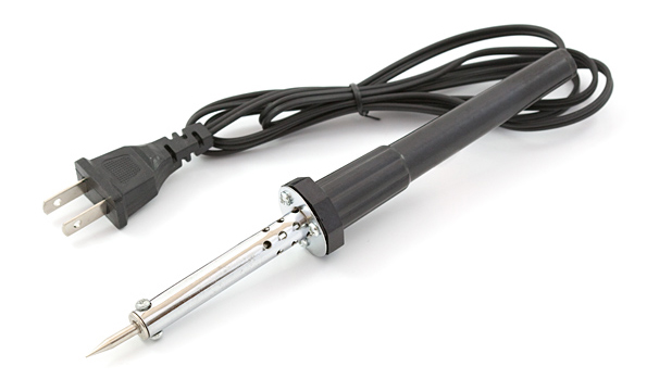 Simple wand — no base
// Soldering Station
A base + wand setup. The base controls temperature. Analog bases use a dial; digital bases show the exact temperature. Some offer heat profiles for different components.
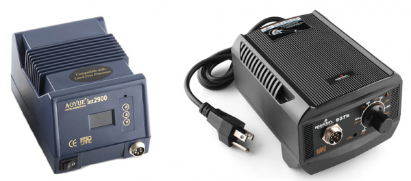 Digital station (left) & analog station (right)
// All irons have the same key parts: tip, wand, and some form of heat source. The station just adds control.
Iron Anatomy — Tips, Stand & Cleaning
// Tip
Heats up and allows solder to flow. The tip transfers heat — not solder. Solder melts because the joint is hot enough, not because solder touches the tip.
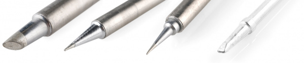 Common tip shapes — chisel, conical, bevel, fine point
// Stand / Cradle
Always rest the iron here when not actively soldering. Prevents burns and fire hazards. Premium stands add auto-shutoff when the wand is cradled.
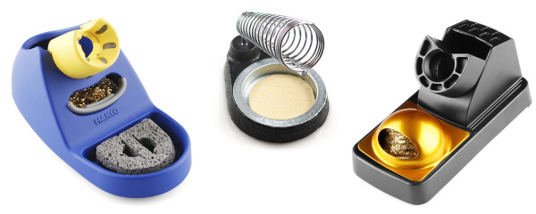 Stand types — sponge cradle, coil stand, brass wool stand
// Brass Sponge (not wet sponge!)
Tips oxidize over time — turning black and rejecting solder. Wipe on a brass sponge: it strips build-up without temperature shock. A wet sponge causes rapid expansion/contraction that eventually holes the tip.
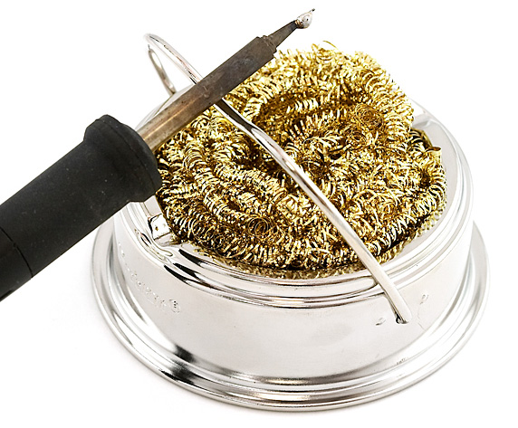 Brass sponge in use
What is wrong with this stock photo?

Soldering Technique
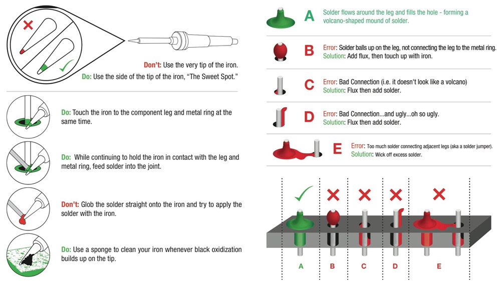
- Be cautious with hot irons.
- Set to 325–375°C (600-700°F). Smoke = too hot.
- Tin your tip before each joint.
- Use the side of the tip, not the point.
- Heat pad AND part together.
- Pull solder first, then iron. Good joint = volcano shape.
Solder Joint Quality
Good Joint
- Shiny, smooth surface
- Volcano / Hershey kiss profile
- Solder wets fully up the pin and across the pad
Cold Solder Joint
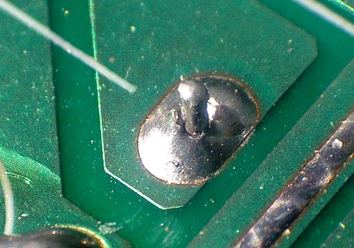
- Dull, grainy or balled-up surface
- Tiny gap between solder and pin — no real connection
- Cause: not enough heat applied to the joint
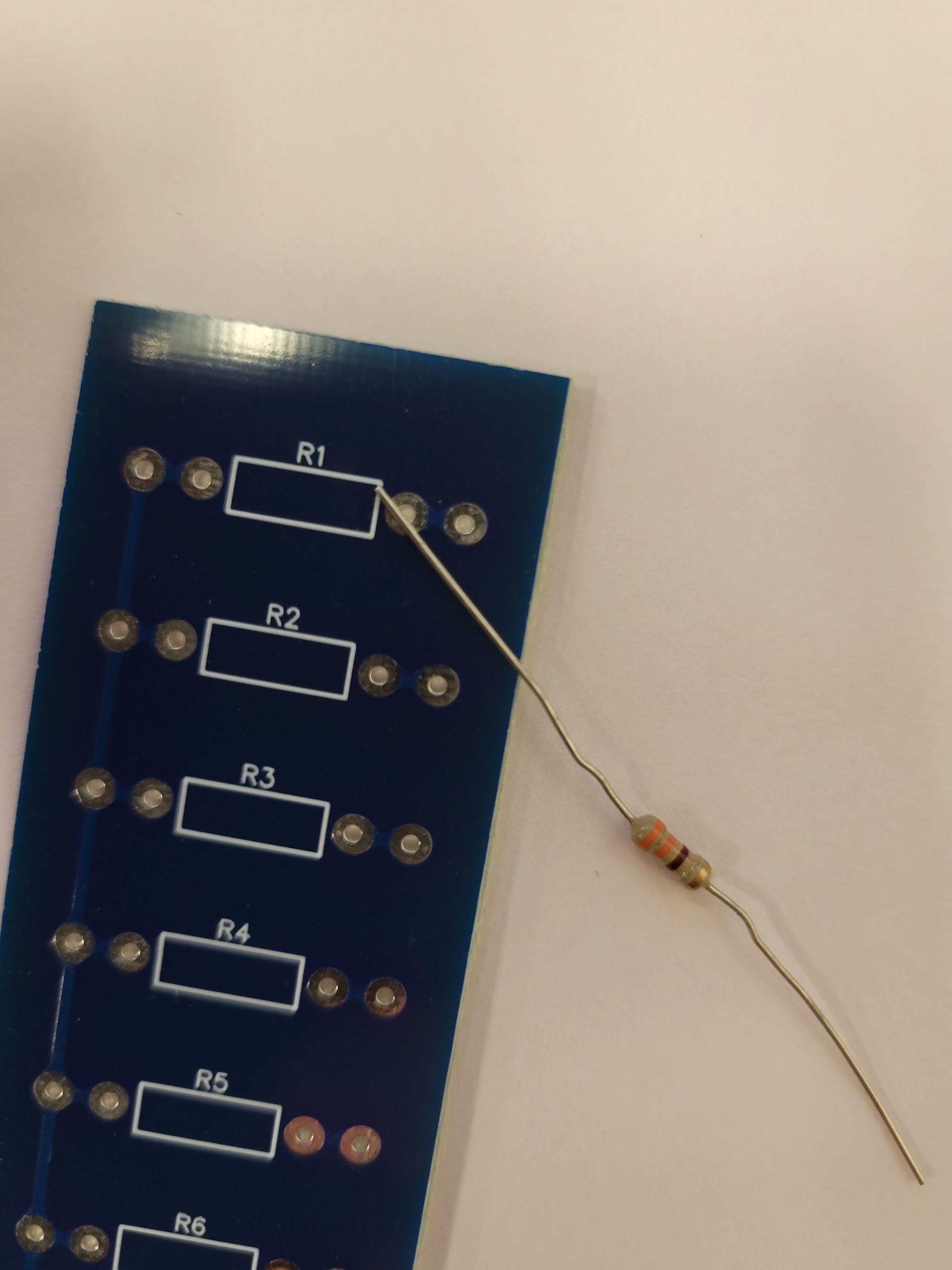
Soldering the Resistor Check Board
- Get 10 resistors from your instructor along with your Resistor Check PCB.
- Bend the leads so they fit through the inner pair of holes on the board. Closer is better, but doesn't need to be exact.
- Place a resistor on the top side of the PCB (the side with the puma logo), leads going through the inner pair of holes.
- On the back side, pull the leads outward to hold the resistor tightly against the board.
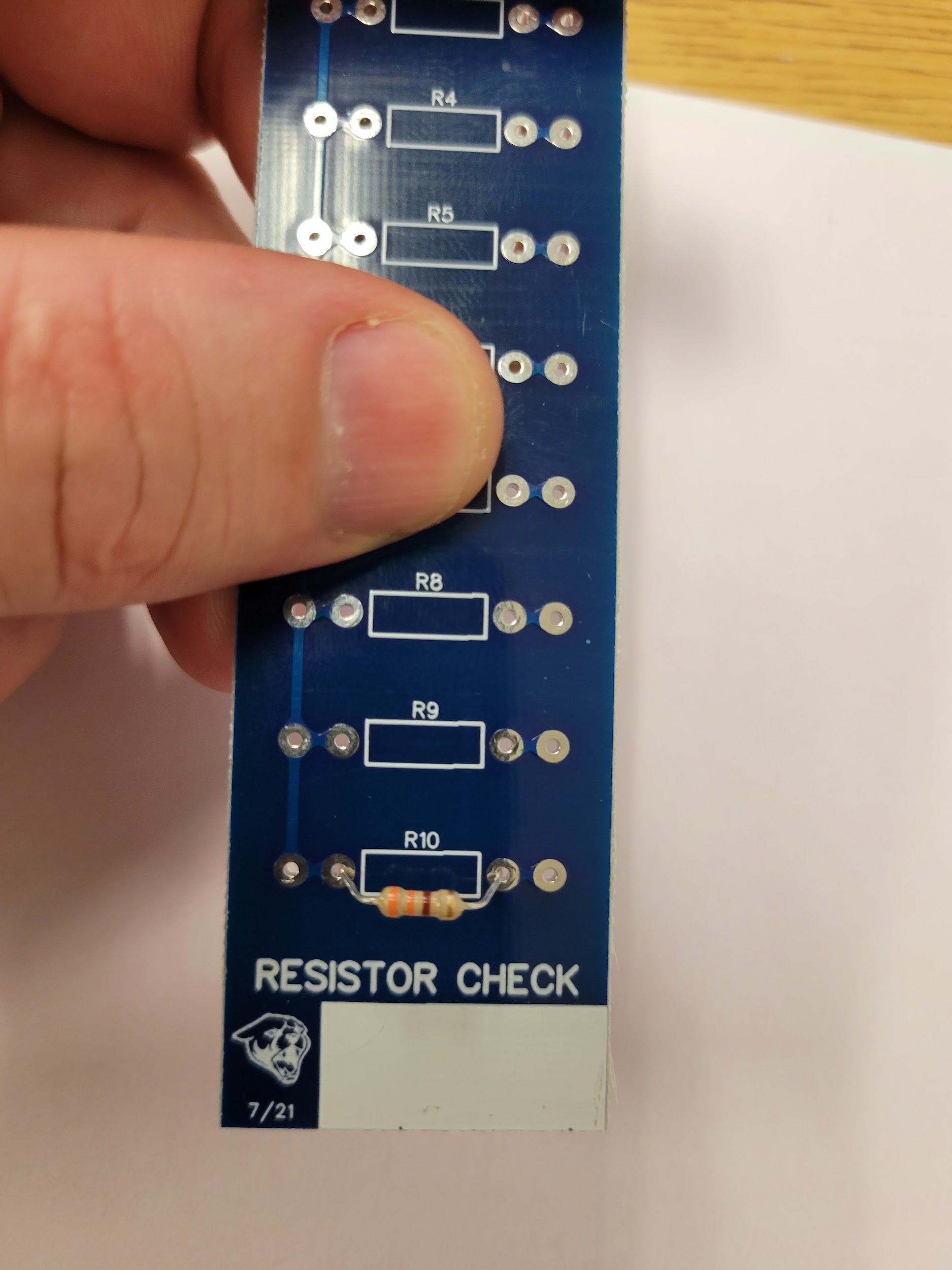
The Resistor Check PCB
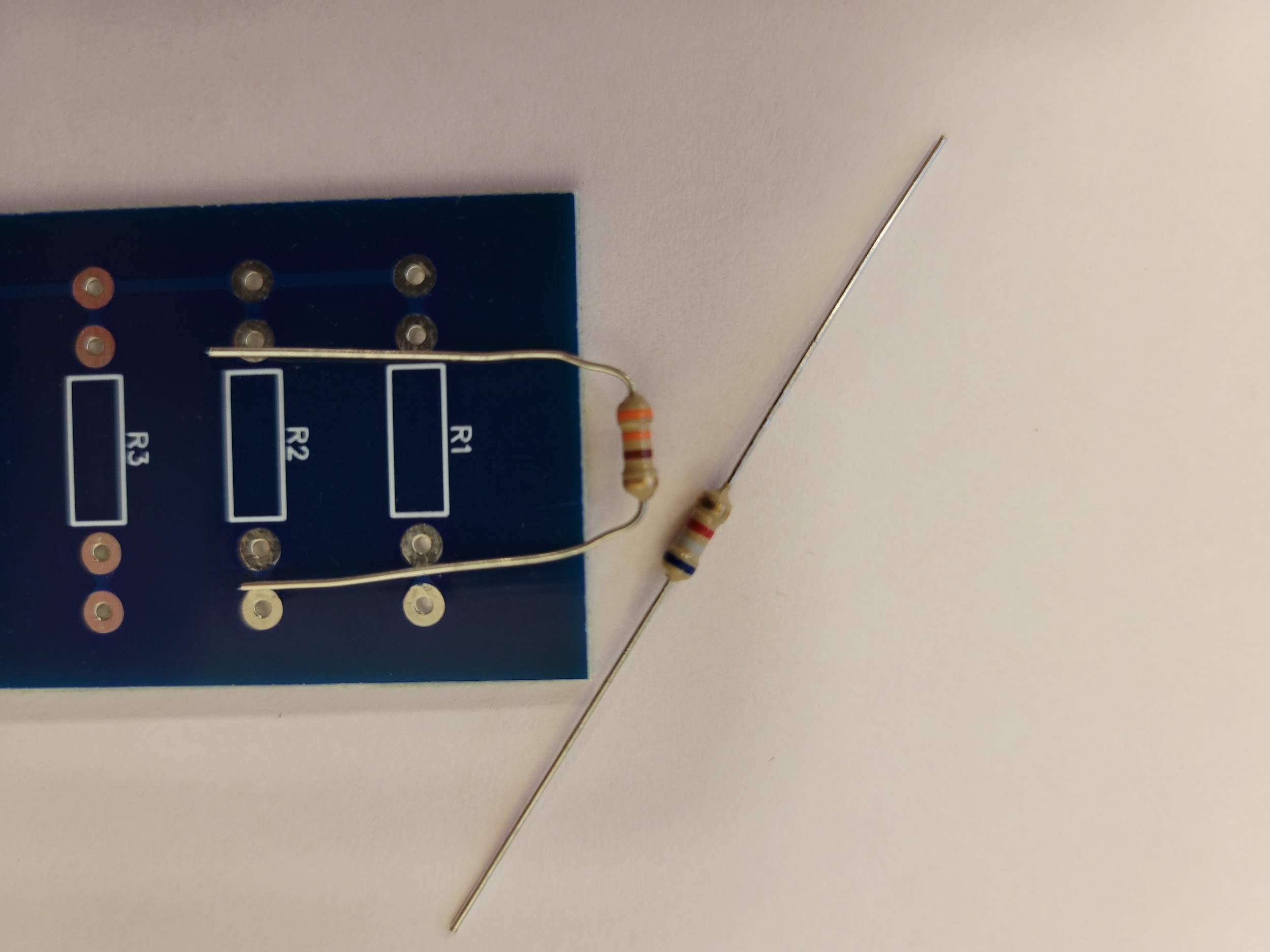 Step 2: Bend the leads
 Step 3: Place on top side
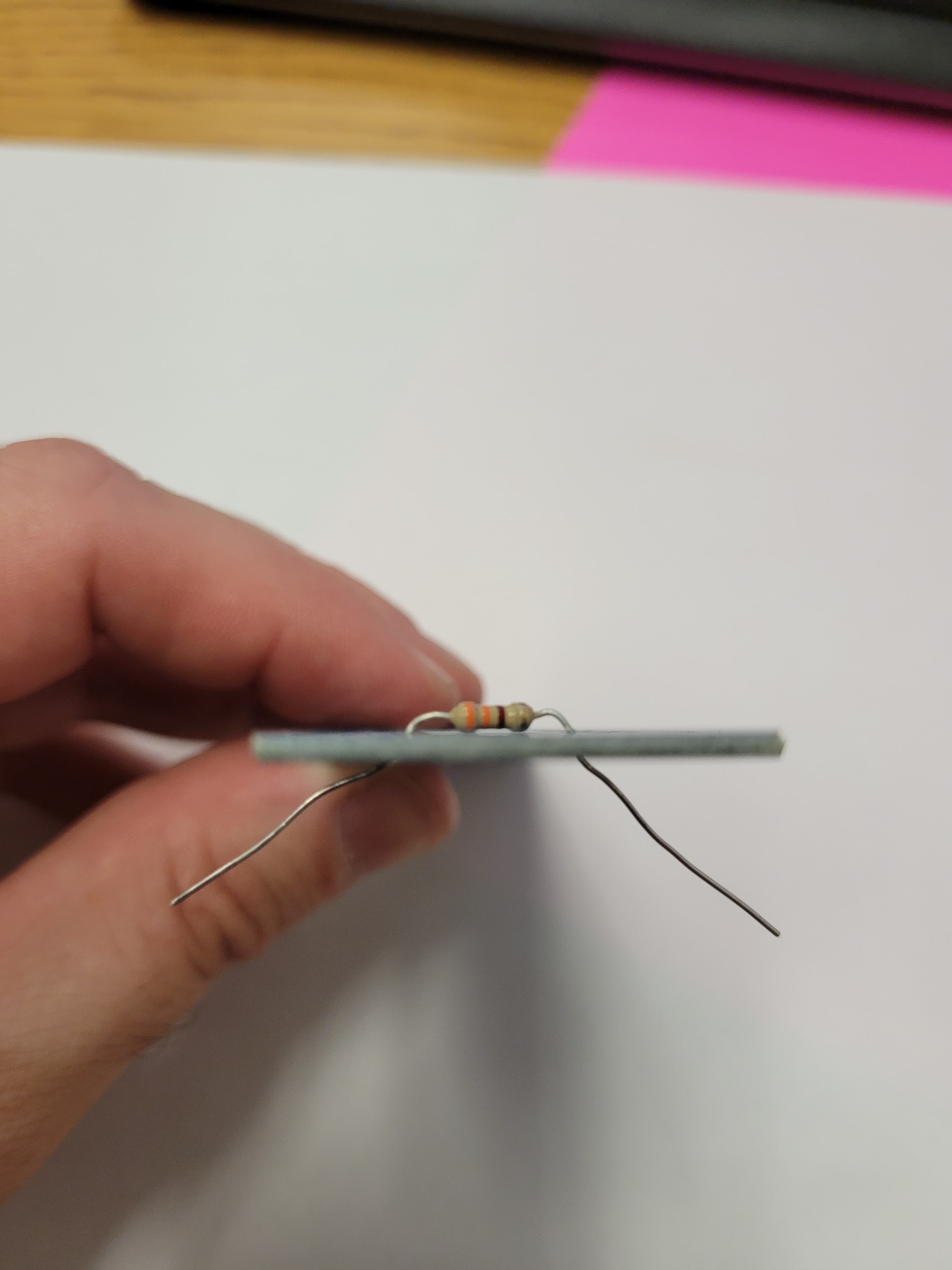 Step 4: Pull leads outward
Soldering the Resistor Check Board
- Flip the board leads-up. Solder both leads to their pads.
- Trim the leads with flush cutters so they barely protrude past the solder joint.
- Repeat for all 10 resistors. When the board is full, show your instructor before measuring.
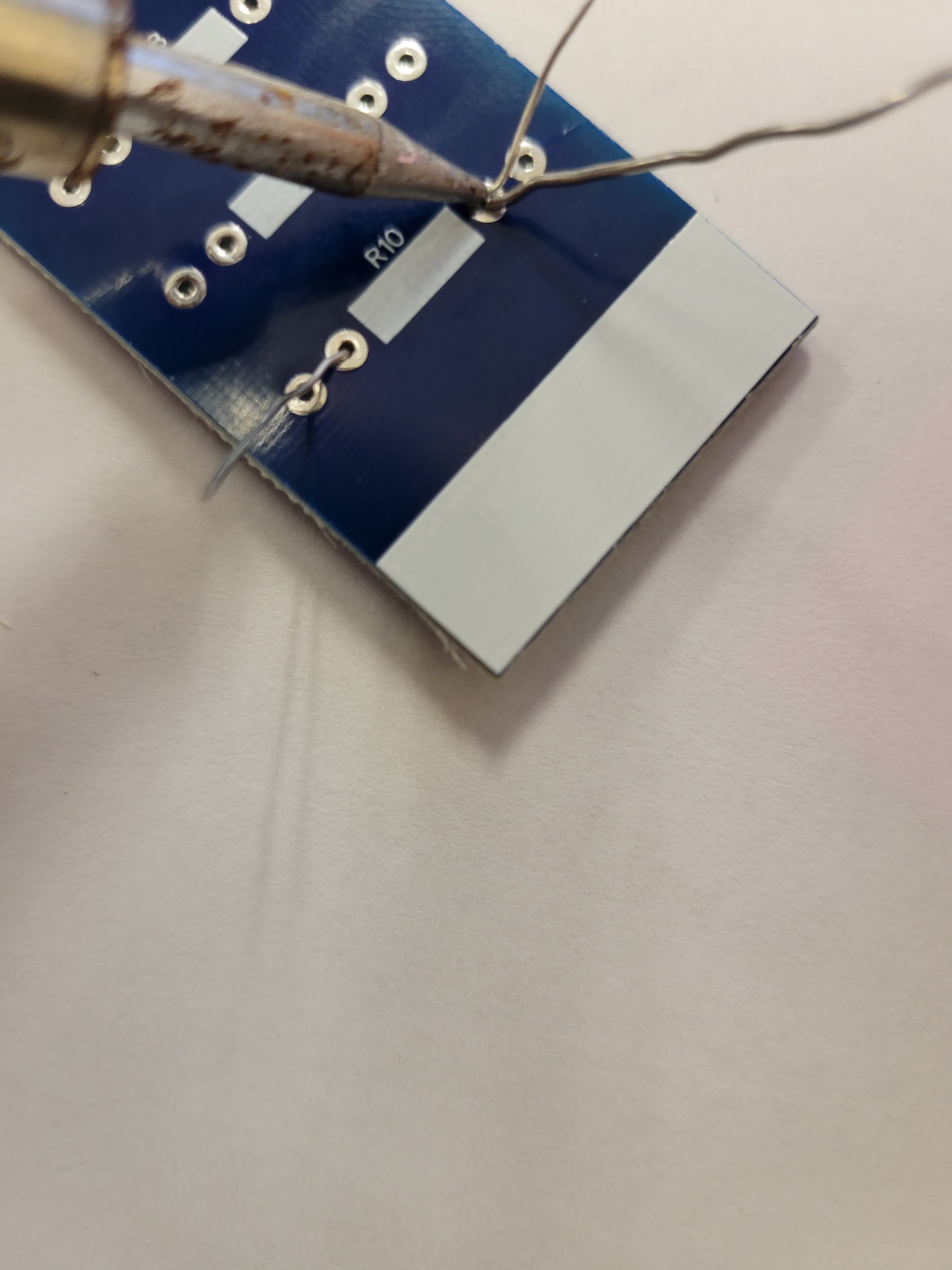 Step 5: Soldering
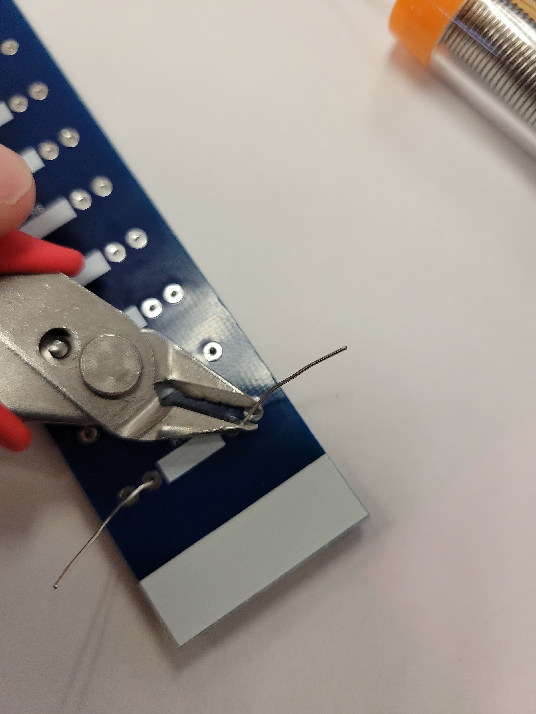 Step 6: Trimming leads
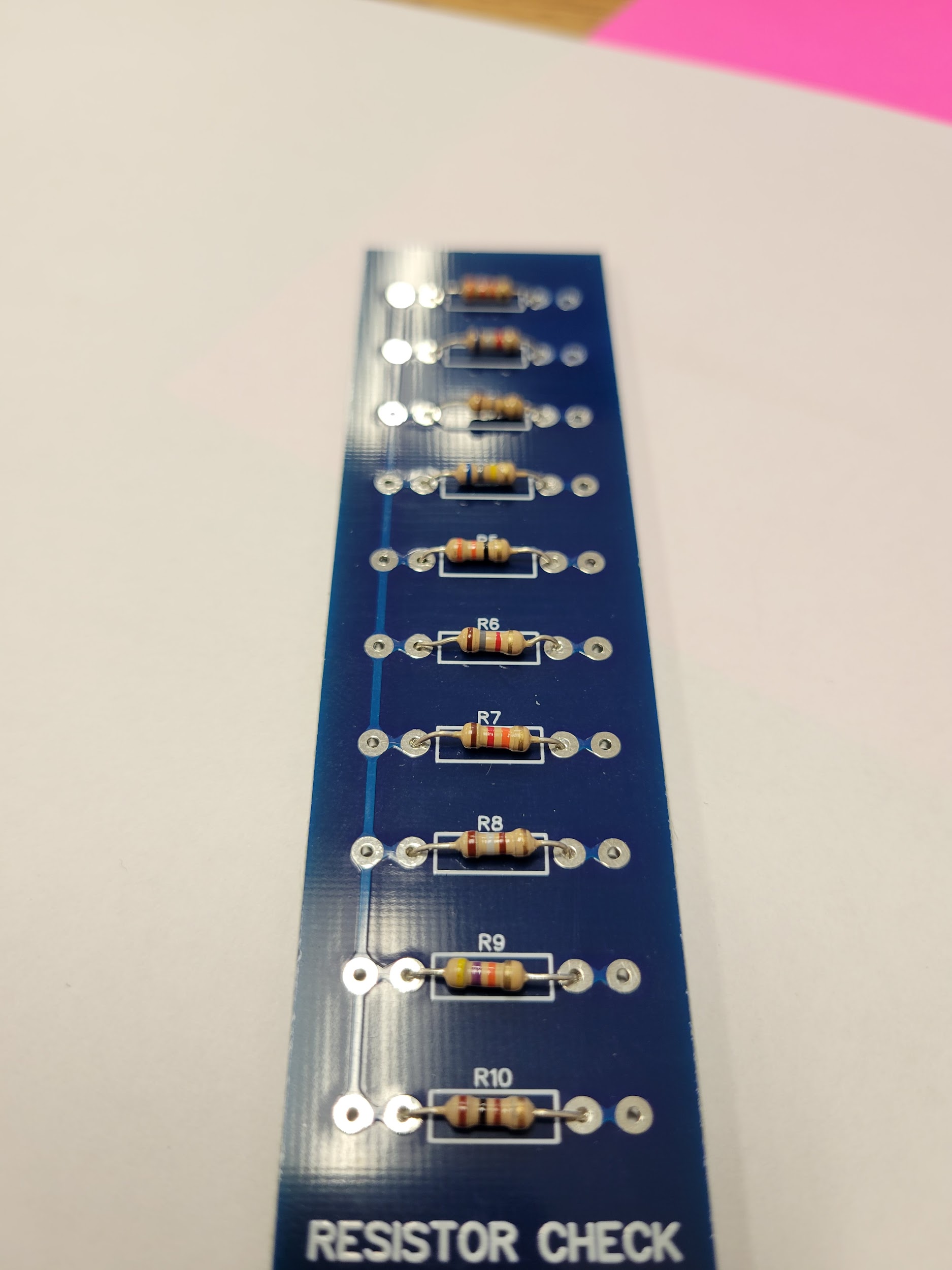 Step 7: All 10 mounted
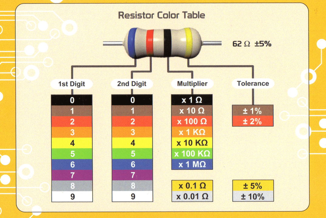
Resistor Color Code
Band 16Blue
Band 22Red
Band 3×10⁰Black
Band 4±5%Gold
- Find Band 1: gold or silver = Band 4. The other end is Band 1.
- Band 1 + Band 2 give the first two digits.
- Band 3 is the multiplier: 10n. Black = ×1, Yellow = ×10,000.
- Band 4 = tolerance. Gold = ±5%.
Blue, Red, Black, Gold
62 × 1 = 62 Ω
±5% → 58.9 Ω to 65.1 Ω