What Is Magnetism?
- A material's property to exert a magnetic force (attraction or repulsion) on another material from a distance
- Ferromagnetic materials are strongly attracted to magnets: primarily iron, nickel, cobalt, and some rare earth metals
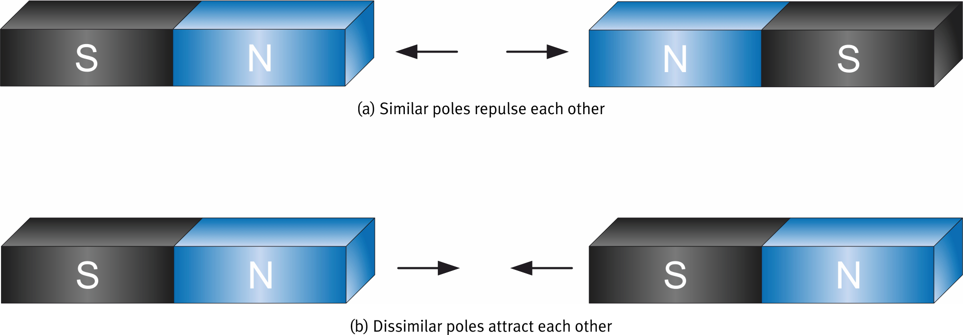
- Every magnet has two poles: North (N) and South (S)
- Opposite poles attract; like poles repel
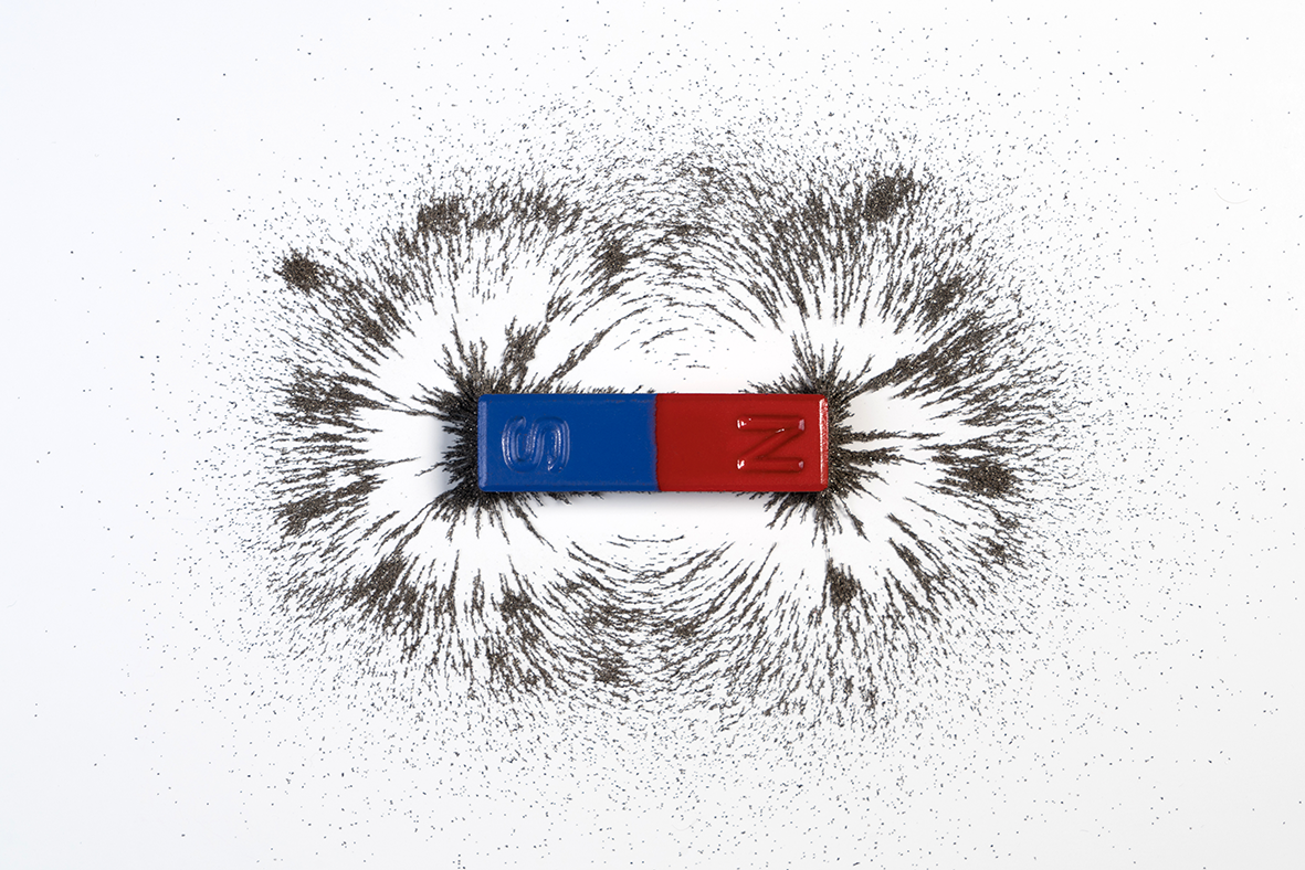
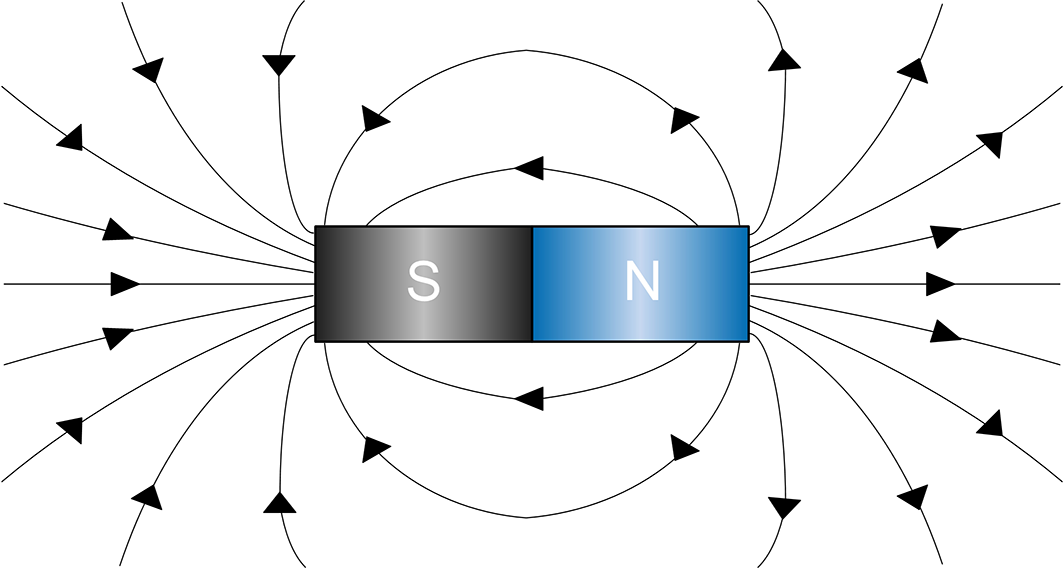
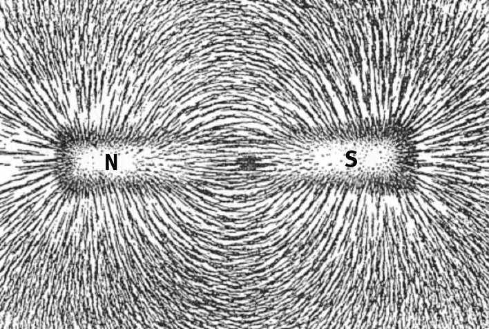
Lines of Force
- Magnetic fields are visualised using lines of force
- Lines exit through the North pole and enter through the South pole
- Iron filings sprinkled around a magnet align along the lines of force, making the field visible
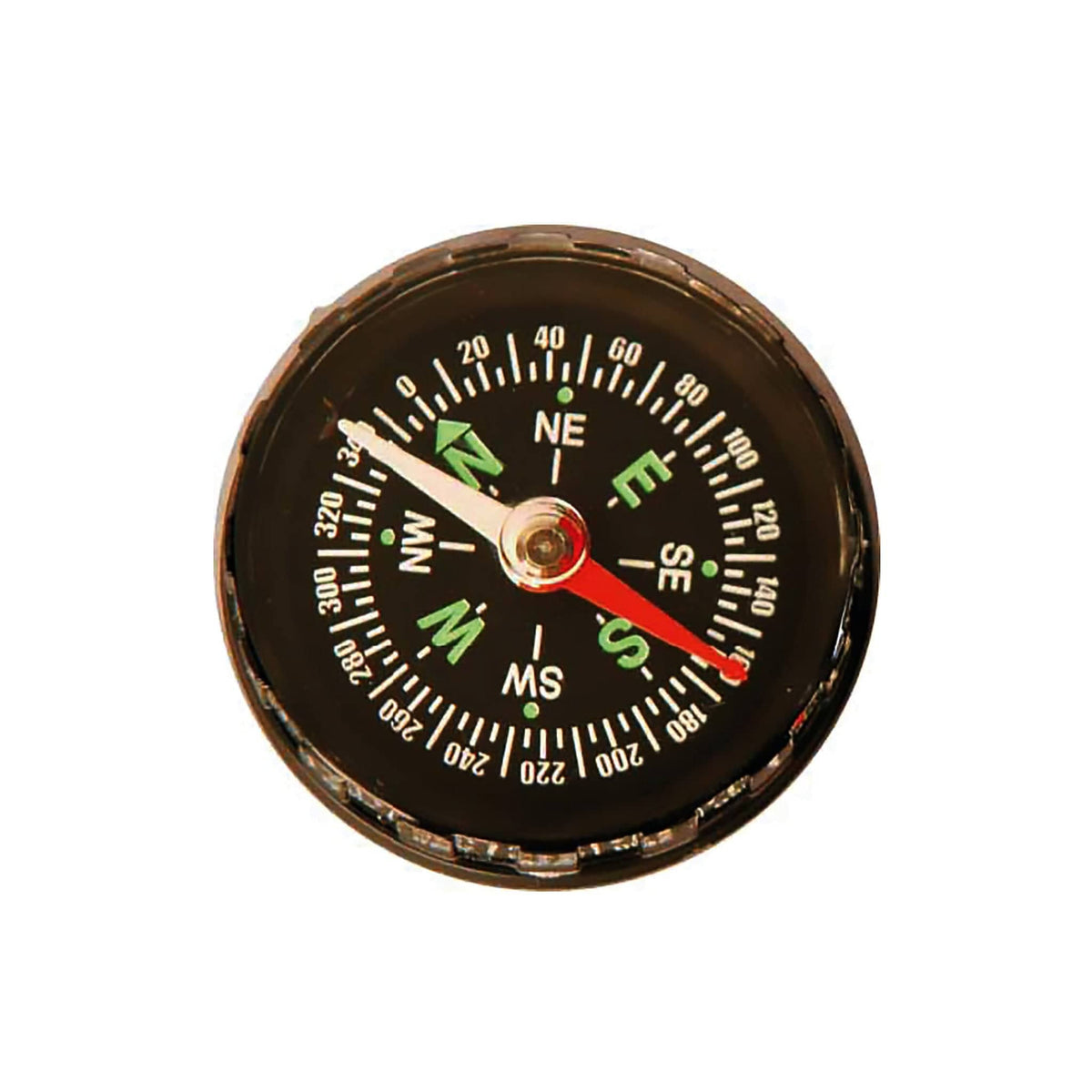
- A compass needle aligns itself along these lines — the red (N) end points toward Earth's magnetic South
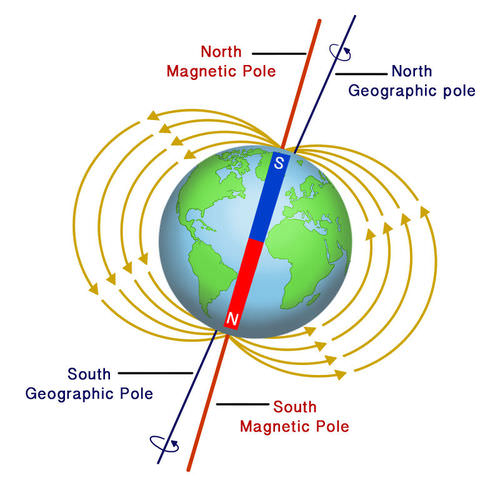
Historical Note
The Earth itself is a giant magnet. Geographic North is actually the Earth's south magnetic pole. Opposite poles attract, so the compass N always points "north."
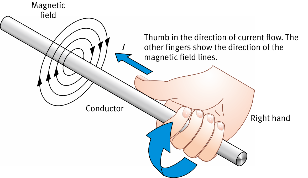
Current Creates a Magnetic Field
- The field is circular and centered on the wire
- Right-hand rule: wrap your right hand around the wire with the thumb pointing in the direction of current flow. Your fingers indicate the direction of the magnetic field lines
- Reverse the current direction → field direction reverses
Key Idea
Electricity and magnetism are two aspects of the same fundamental force: electromagnetism.
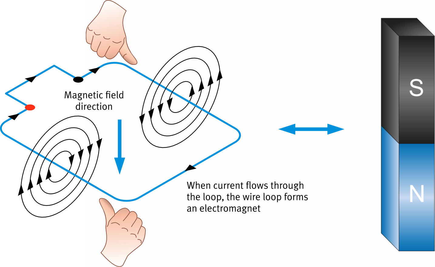
The Electromagnet
- Current in a loop of wire produces north and south magnetic poles
- Use the right-hand rule to find the field direction inside the loop → locate N and S
- More current → stronger magnetic field
- No current → field disappears instantly — unlike natural magnets
Advantage Over Natural Magnets
An electromagnet can be turned on and off, reversed, and its strength controlled by adjusting the current.
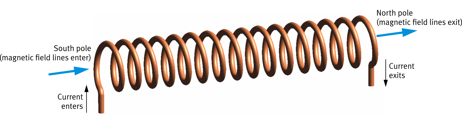
The Solenoid
- A wire wound in the form of a helix is called a solenoid
- Each loop produces a field in the same direction. They all add together
- Total field ≈ field of one loop × number of loops
- The center of the solenoid is called the core
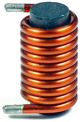
Iron Core Upgrade
Replacing the air core with an iron core greatly increases the magnetic field strength. These are what most people mean by "electromagnets."
Solenoid with a Plunger
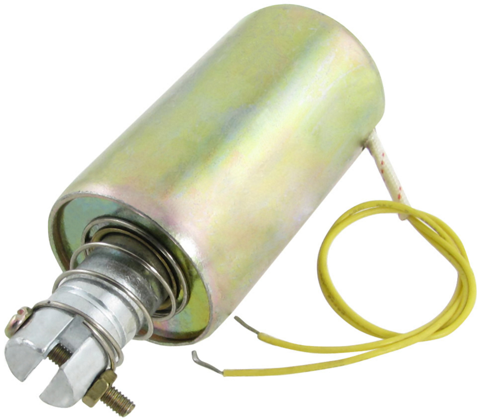
Current ON → solenoid field strongly attracts the plunger into its center
Current OFF → field disappears; a spring returns the plunger to its rest position
Converts electrical energy → linear mechanical motion
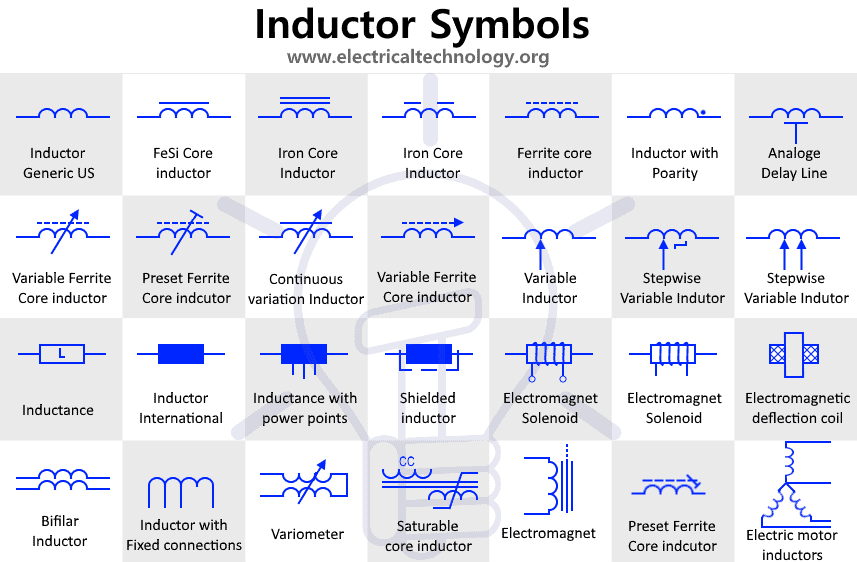
Symbol
 Among others
Real-World Applications
Door bells — plunger strikes a chime
Magnetic locks — plunger engages/releases a latch
Circuit breakers — trips when overcurrent detected
Relays — low-power signal switches high-power circuit
Valves — controls fluid or gas flow
Magnetic brakes — used in cranes, elevators
Magnet cranes — lift and release metallic materials
DC Motor Construction
Stator — Fixed outer shell. Contains a pair of magnets with opposite poles facing each other, creating a field across the armature.
Rotor (Armature) — Rotating part. Made of one or more wire loops wound on a metallic armature.
Commutator — Segmented ring connected to the wire loops. Reverses current direction in the loop as the rotor spins.
Brushes — Stationary contacts that slide on the commutator, providing a continuous electrical connection to the rotating loops.
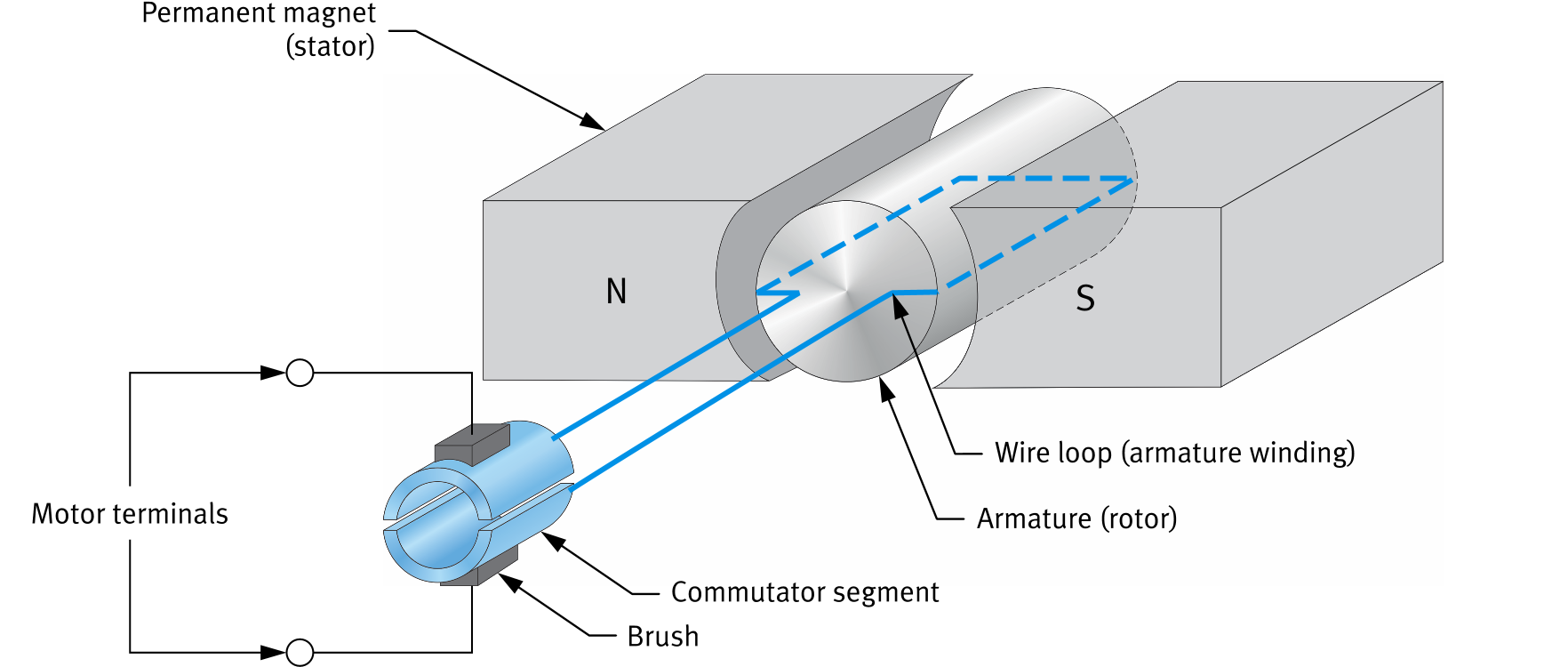
How the Motor Spins
1 — Current flows in the armature wire loop → creates an electromagnet (N and S poles on the rotor)
2 — The rotor's poles are attracted and repelled by the stator's fixed poles → rotation begins
3 — As the rotor turns, the commutator switches which loop carries current.
4 — This keeps the force in the same rotational direction → continuous spinning
Key Result
The N and S poles of the armature electromagnet oscillate, maintaining the same rotational direction even as the armature rotates.
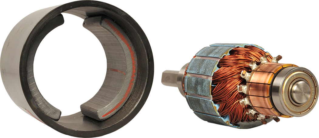
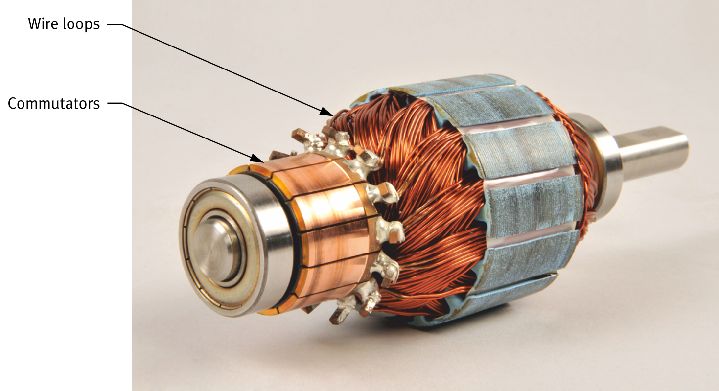
Real Motors
Actual DC motors use multiple wire loops and commutator segments for smoother, more consistent torque.
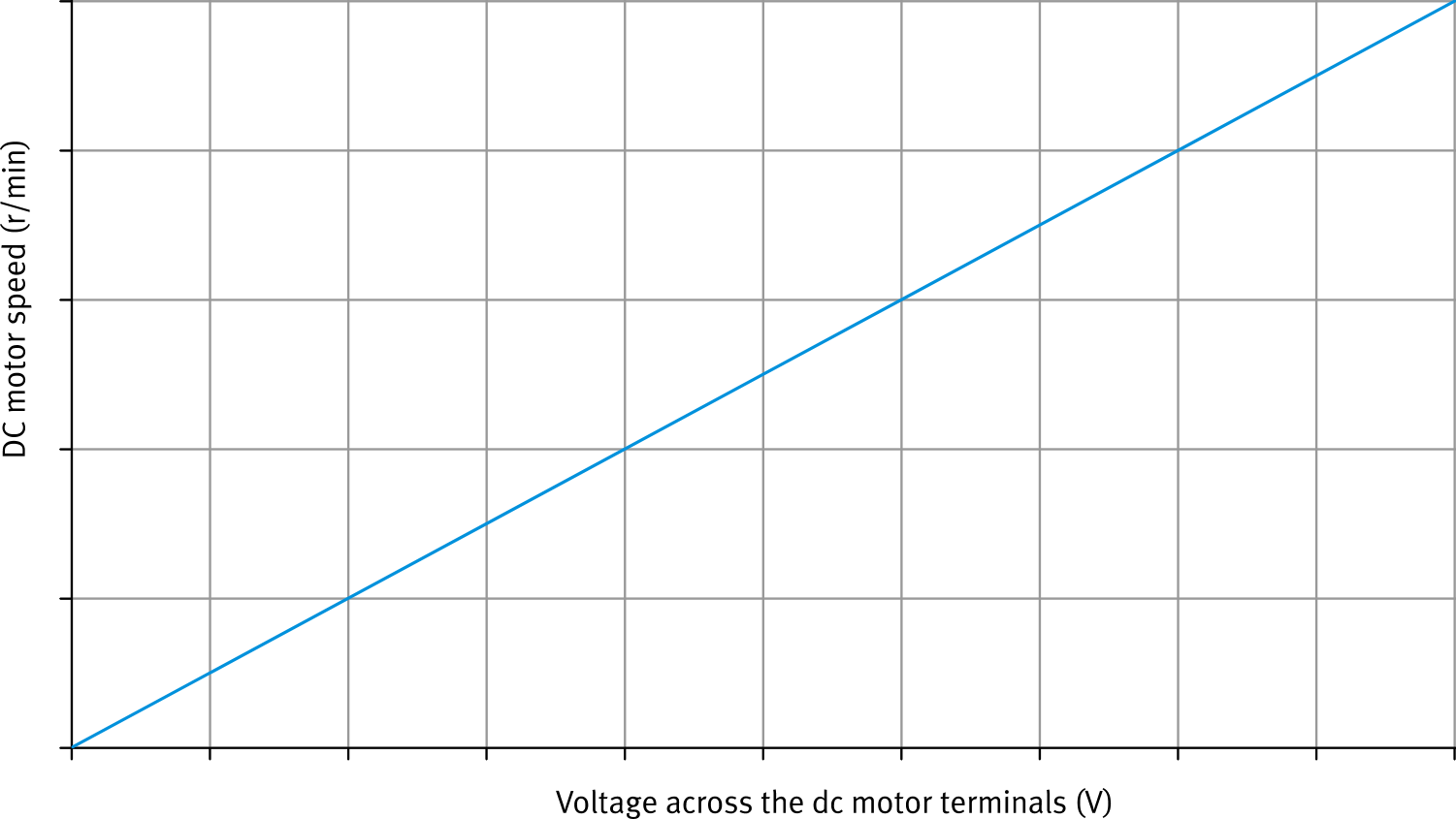
Speed vs Voltage
- Speed is directly proportional ( ∝ ) to voltage — double the voltage, roughly double the speed
- Higher voltage → stronger current → greater force on armature → faster rotation
- Speed control is simple: adjust the supply voltage with a variable resistor or power supply