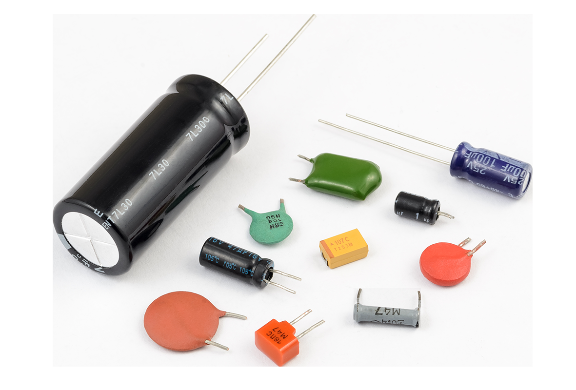
What Is a Capacitor?
- Consists of two conducting materials (plates) separated by an insulating material called a dielectric (e.g., glass, air, paper)
- Unlike resistors, capacitors do not convert power to work — they store electrical energy in an electric field
- Main property: oppose voltage changes in a circuit
- A pair of terminals provides access to the conducting plates
Key Difference
Resistors use almost all power supplied to them. Capacitors store it instead.
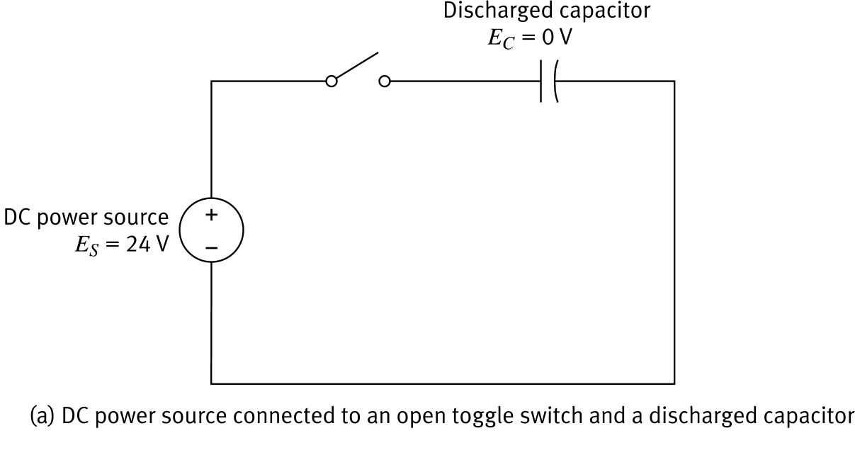
Charging a Capacitor
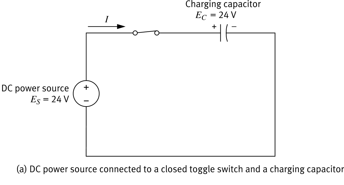
Switch closes → current flows from the power source into the capacitor
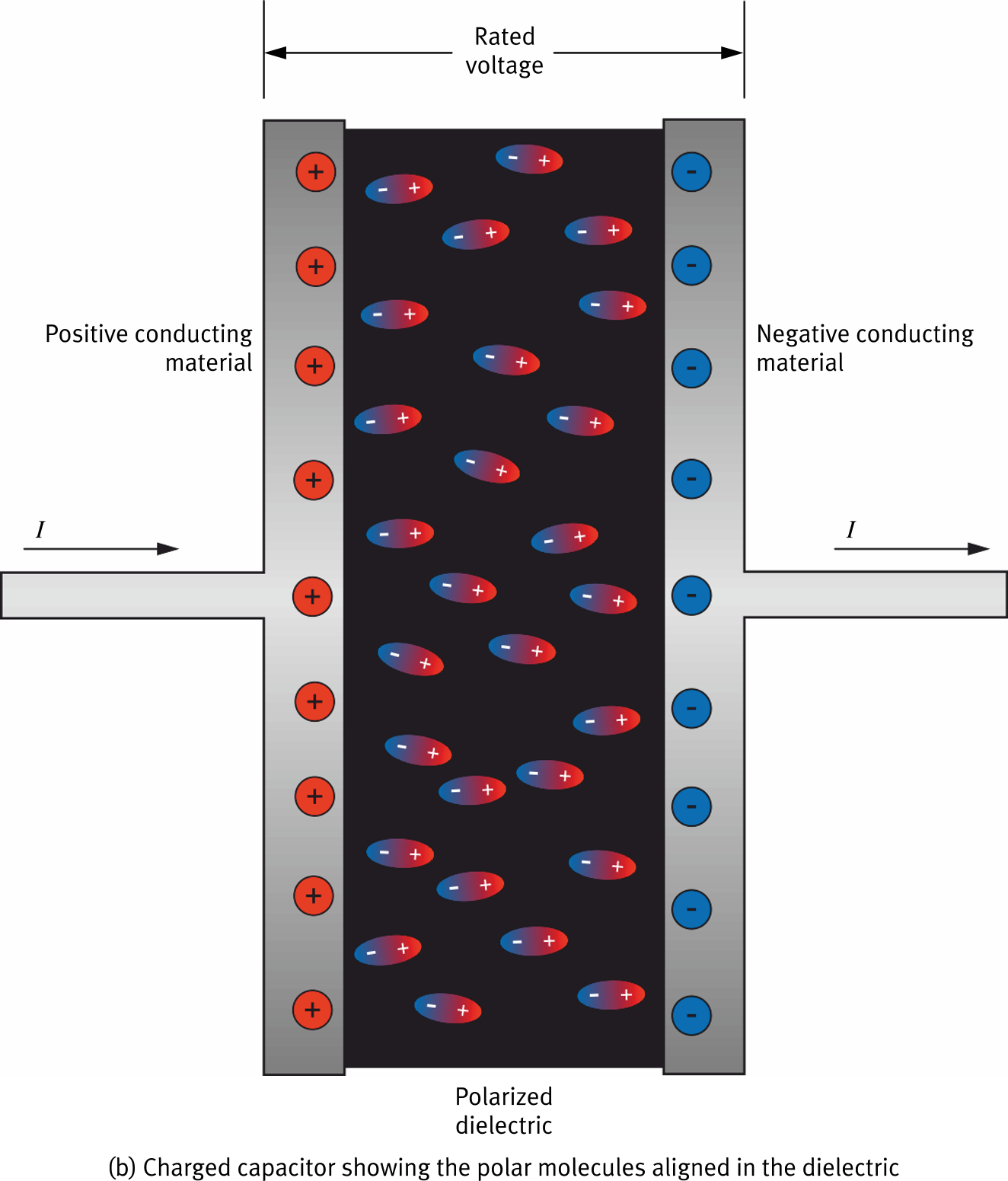
Conducting material on the positive side becomes positive; negative side becomes negative
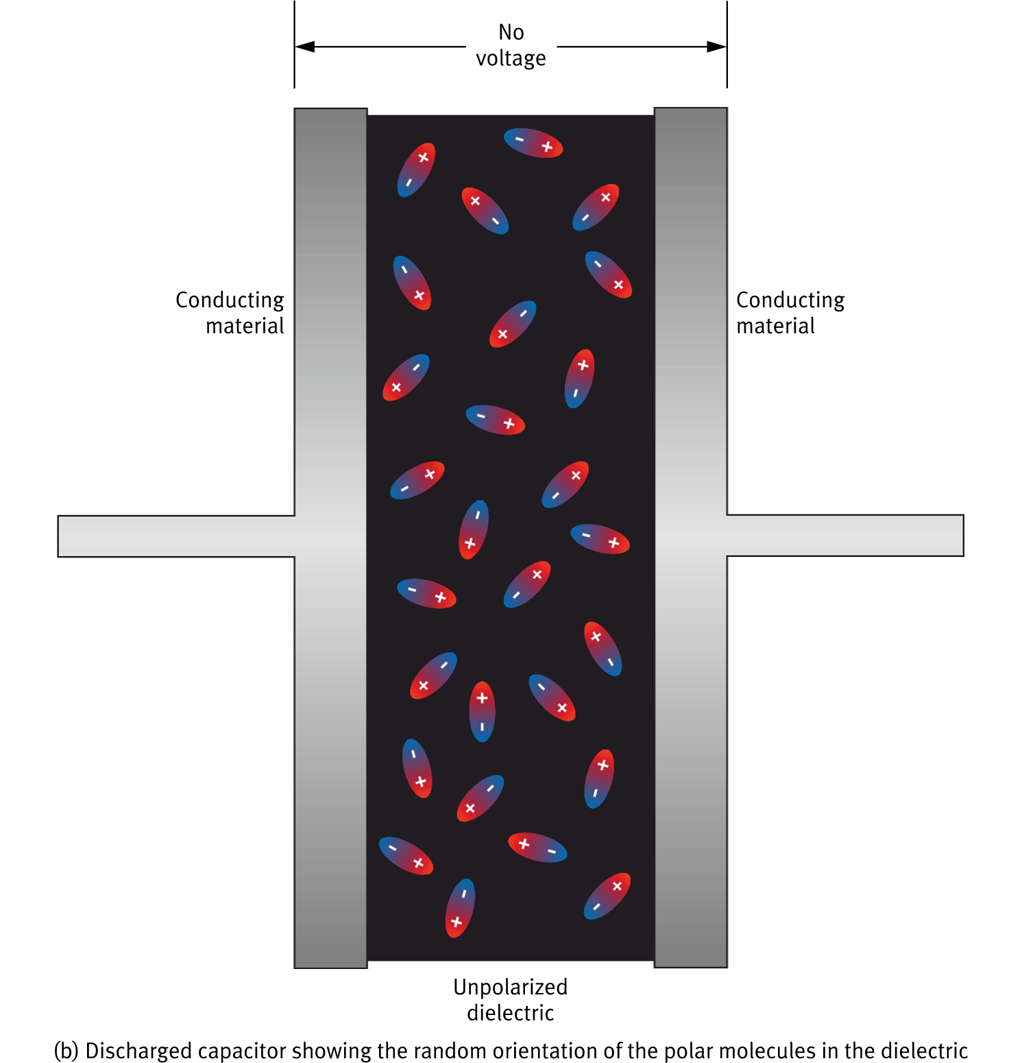
Polar molecules in the dielectric align with the electric field — this is polarisation
Aligning the dielectric increases capacitance by reducing the effective field between the plates
When the charge inside the capacitor equals the source voltage (EC = ES), the capacitor is fully charged and current stops
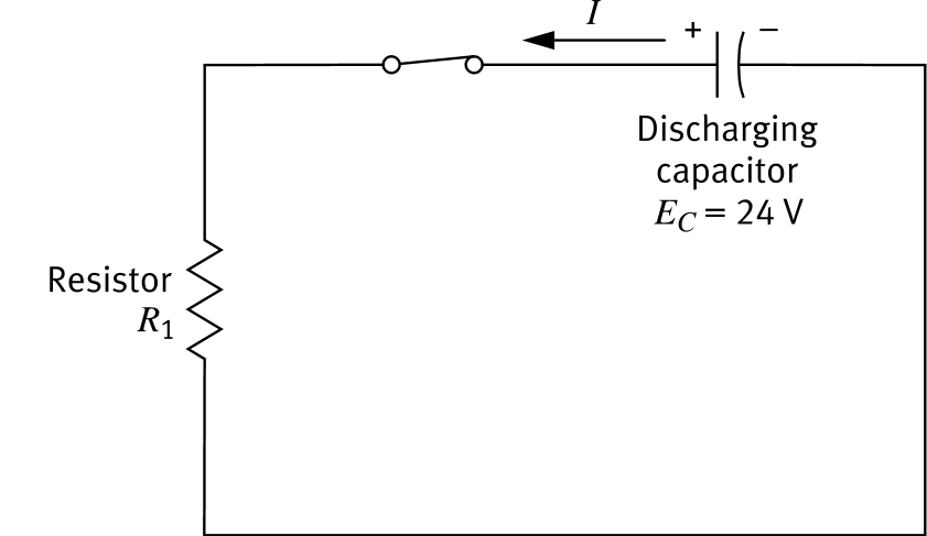
Discharging a Capacitor
- A charged capacitor connected to a resistor acts as a DC power source — it drives current through the circuit
- Discharge current flows in the opposite direction to charge current
- The capacitor voltage drops and current decreases until both reach 0
Capacitor Leakage
In theory a charged capacitor holds its charge when disconnected. In practice, the voltage decreases slowly over time due to self-discharge (leakage).
Capacitance C
Unit: Farad (F)
1 µF = 10−6 F (microfarad — most common)
1 nF = 10−9 F (nanofarad)
1 pF = 10−12 F (picofarad)
Voltage Rating
Each capacitor has a working voltage — the maximum safe voltage. Exceeding it can deform the plates or cause the capacitor to explode.

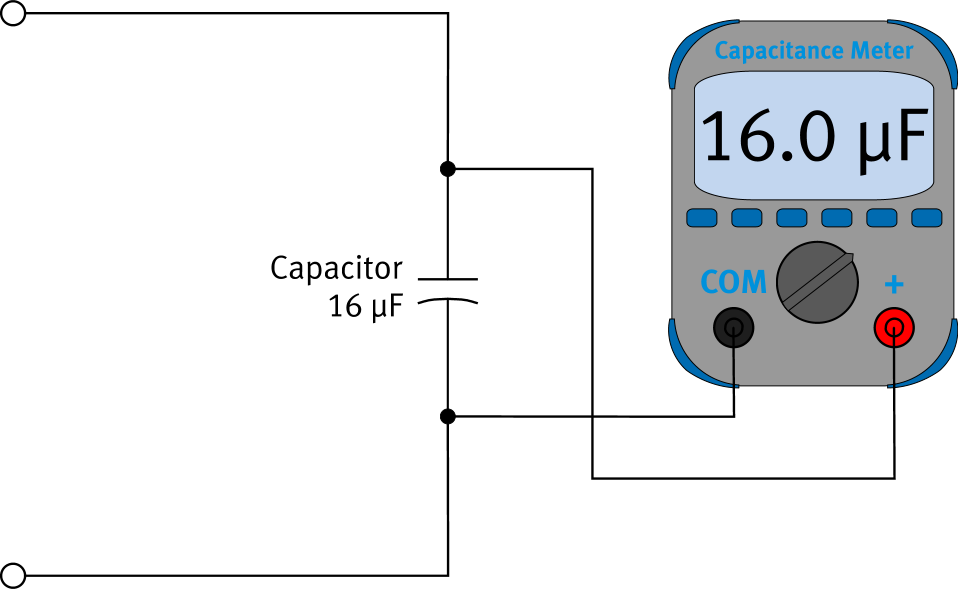
Using a Capacitance Meter
1 — Power off the circuit before measuring
2 — Connect the capacitance meter in parallel with the capacitor under test
3 — Read the capacitance value (in µF or nF)
Important
Never use a capacitance meter in a live circuit — it will give inaccurate readings and may be damaged. Also note that capacitors have a tolerance, like resistors.
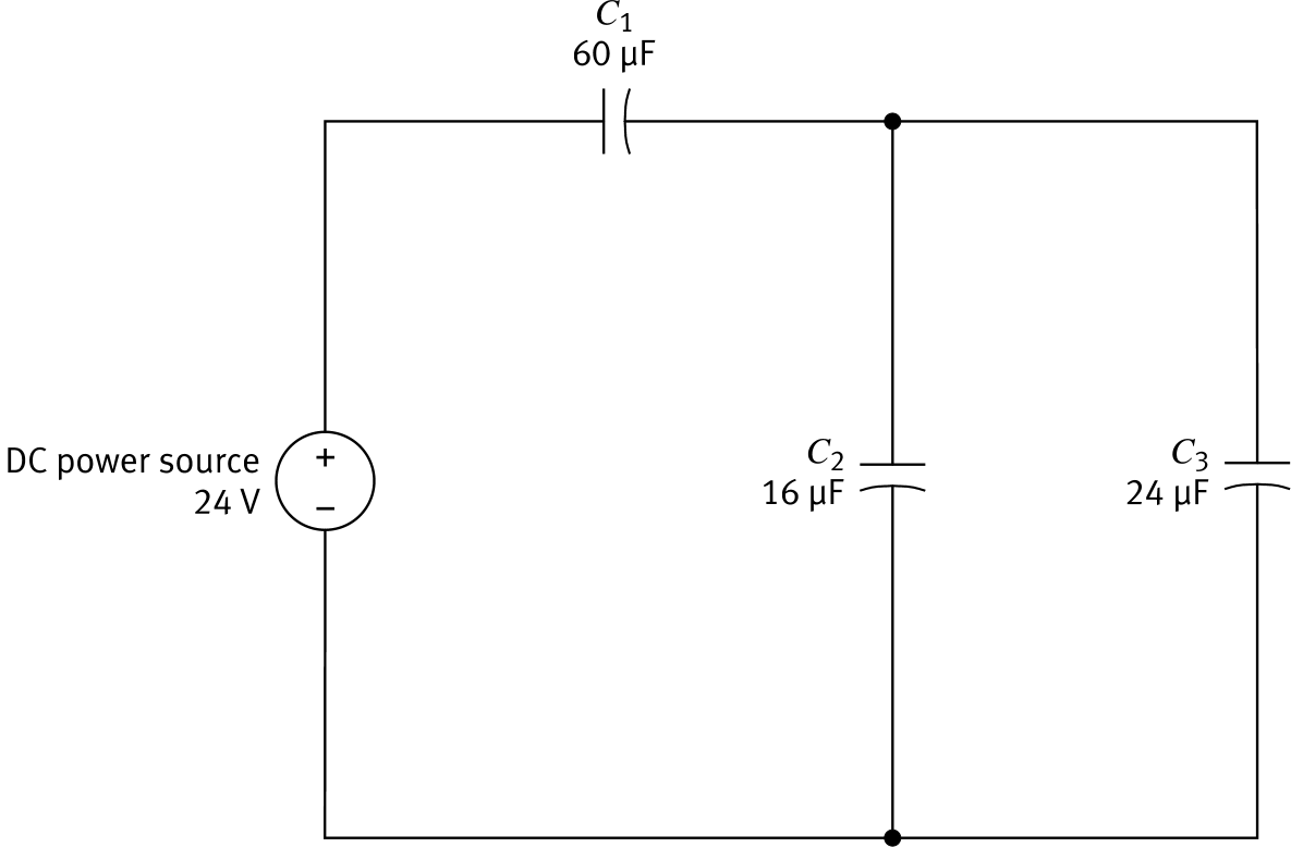
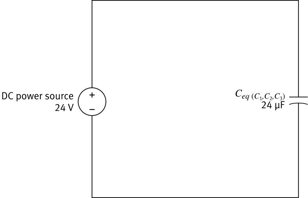
Mixed Capacitor Circuit
Note
Capacitor combinations are the opposite of resistors: series = smaller total; parallel = larger total.
Mixed Capacitor Circuit
Series Formula
1Ceq = 1C₁ + 1C₂ + …
Parallel Formula
Ceq = C₁ + C₂ + …
Note
Capacitor combinations are the opposite of resistors: series = smaller total; parallel = larger total.
1
Combine C₂ ∥ C₃ (Parallel)
Parallel Formula
Ceq(C₂,C₃) = C₂ + C₃
1
Combine C₂ ∥ C₃ (Parallel)
C₂ = 16 µF, C₃ = 24 µF
Ceq(C₂,C₃) = C₂ + C₃
Ceq(C₂,C₃) = 16 + 24
Ceq(C₂,C₃) = 40 µF
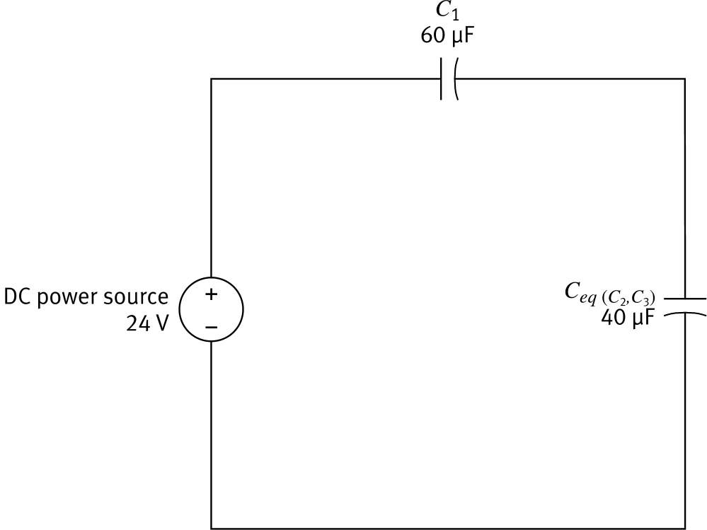
2
Combine C₁ + Ceq (Series)
Series Formula
1Ceq = 1C₁ + 1Ceq(C₂,C₃)
2
Combine C₁ + Ceq (Series)
C₁ = 60 µF, Ceq(C₂,C₃) = 40 µF
1Ceq = 160 + 140
= 2120 + 3120 = 5120
Ceq = 1205
Ceq(C₁,C₂,C₃) = 24 µF
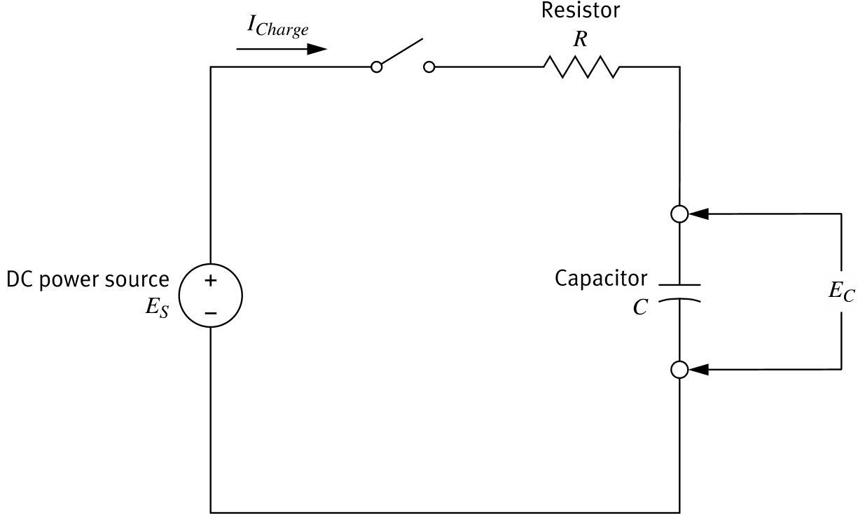
The RC Circuit
Time Constant τ (tau)
τ = R × C
τ in seconds | R in ohms (Ω) | C in farads (F)
| Charge time | Capacitor charged to |
|---|---|
| 1τ | 63% of ES |
| 2τ | 86% of ES |
| 3τ | 95% of ES |
| 5τ | ≈ 100% — fully charged |
Capacitor Voltage & Current During Charge
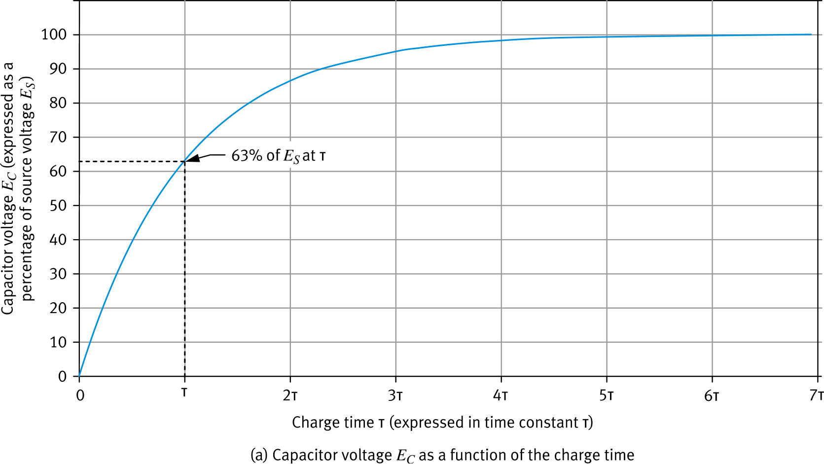
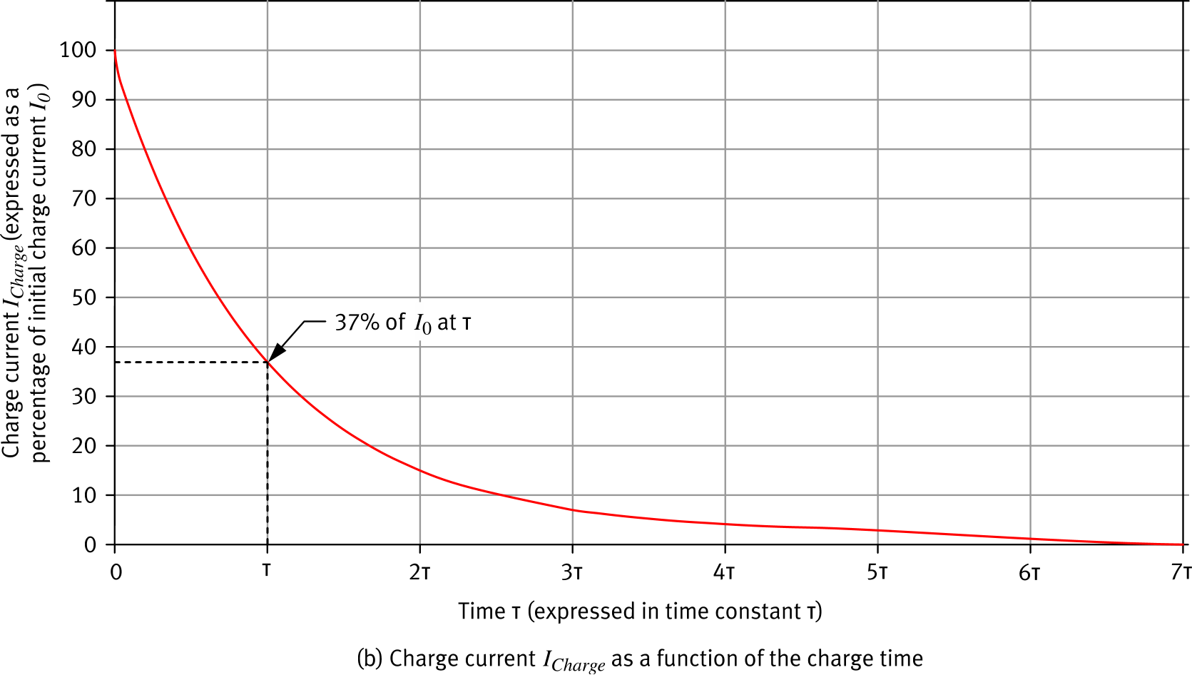
Key Insight
As EC rises toward ES, the current decreases — less voltage difference means less driving force. Both curves take 5τ to complete.
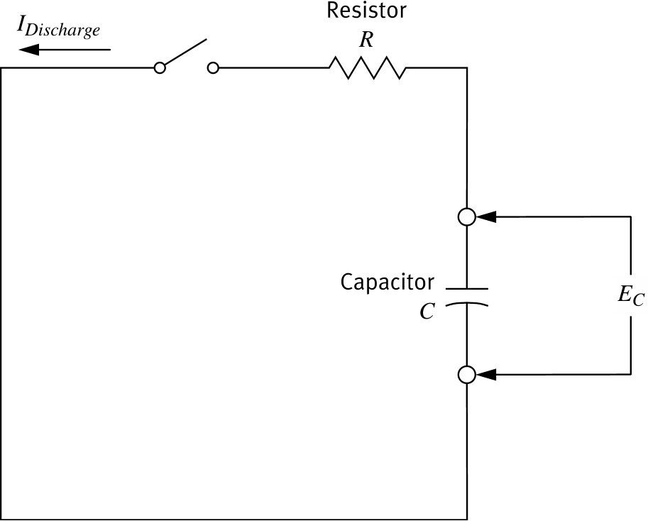
Discharging the RC Circuit
- The capacitor applies its voltage EC to the circuit
- A discharge current flows — in the opposite direction to the charge current
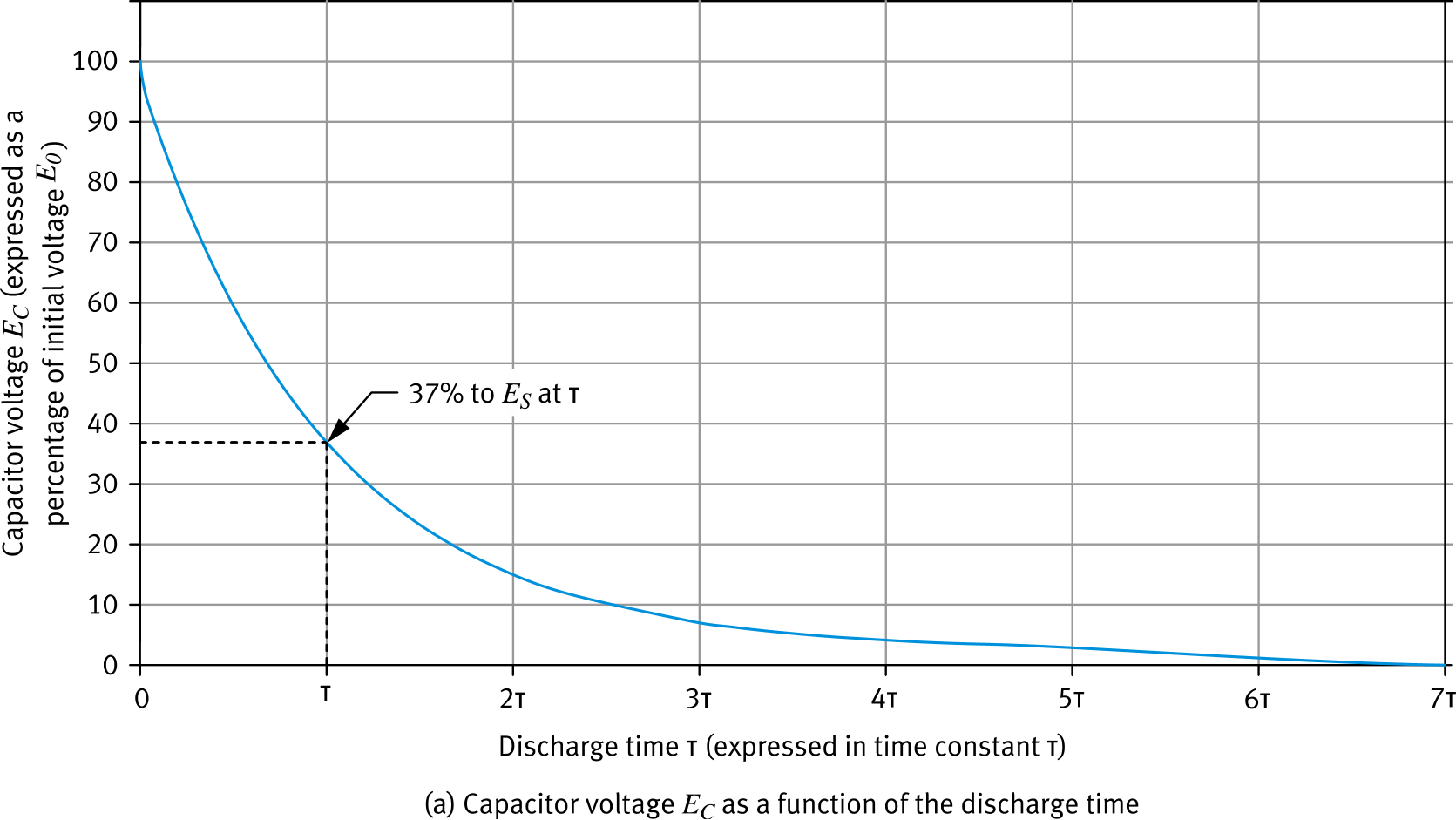
- EC decreases exponentially, as does the discharge current
- After 5τ, the capacitor is considered fully discharged: EC ≈ 0 V, IDischarge ≈ 0 A
Same time constant applies
τ = R × C
Capacitor Voltage & Current During Discharge
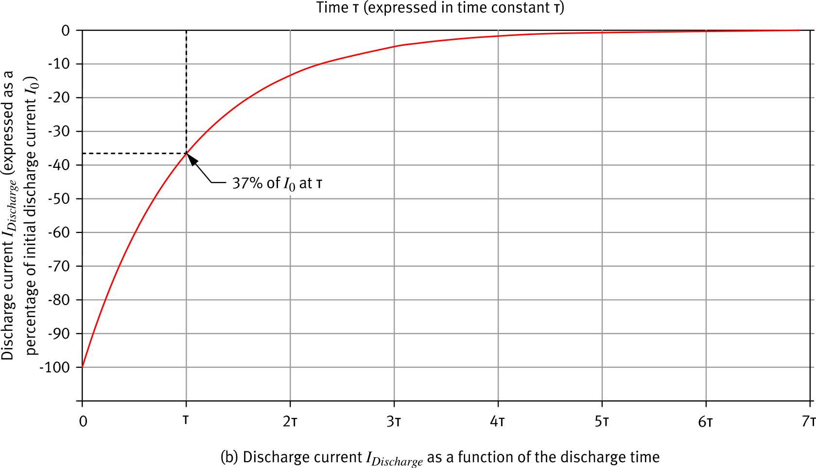
Note on Current Direction
The discharge current is shown as negative — it flows opposite to the charge current. Its magnitude decays the same way as the voltage.
Applications in DC Circuits
- Energy storage — store charge at one voltage, release it as a momentary power source
- Camera flash — electrical energy stored in the capacitor discharges in a very short time through the flashbulb
- Voltage spike absorption — capacitors oppose sudden voltage rises, protecting equipment from high current surges
- Timer circuits — RC time constant defines operating and delay times in time-delay relays and timers
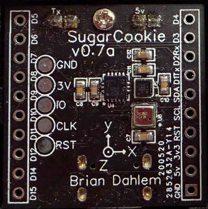
The Capacitor in the AC/DC Training System
Component Specifications
2 × capacitor: 8.8 µF (tolerance ±3%)
1 × capacitor: 4950 µF (tolerance ±20%)
Voltage rating: 230 V max
- Do not exceed 230 V — the capacitor will be damaged
- The large 4950 µF capacitor stores significantly more energy
Lab Safety Checklist
✓ Power off the circuit before connecting or disconnecting capacitors
✓ Verify voltage does not exceed the 230 V rating
✓ Discharge capacitors before measuring or reconfiguring
✓ Use a capacitance meter to verify values before use
✓ Report any swollen, warm, or leaking capacitors immediately
Electrical Hazard
Follow the discharge procedure before any manipulation involving capacitors. This ensures capacitors are fully discharged and prevents electrical shock from residual charge.