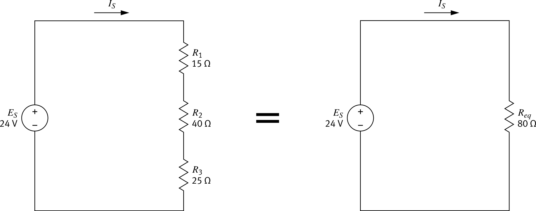
Example Series Circuit Simplification
-
Step 1 — Equivalent Resistance
Req = R1 + R2 + R3
Req = 15 Ω + 40 Ω + 25 Ω
Req = 80 Ω -
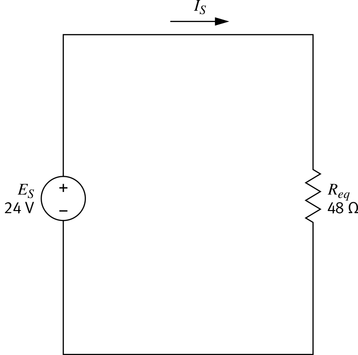
Step 2 — Circuit Current (Ohm's Law)
IS = ES / Req
IS = 24 V / 80 Ω
IS = 0.30 A -
Both circuits carry the same 0.30 A. They have the same Req of 80 Ω.
Kirchhoff's
Voltage Law
Described by German physicist Gustav Kirchhoff, this law is fundamental to the study of series circuits.
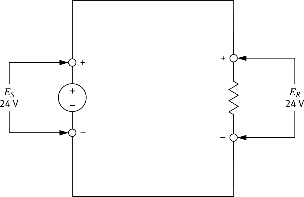
The sum of all voltages in a
closed circuit loop equals 0 V
closed circuit loop equals 0 V
In practice: the sum of the voltage drops across all loads equals the supply voltage.
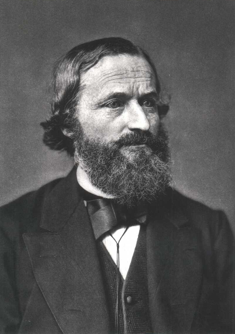 Gustav Kirchhoff (1824 – 1887)
Voltage Drops and Polarity
- Voltage across a passive element (resistor) is a voltage drop
- Its polarity is inverted with respect to the power source
- If source voltage is +24 V, the voltage across the load is −24 V
- The + terminals oppose each other in the circuit (+ against +, − against −)
ES + ER = 0 V
24.0 V + (−24.0 V) = 0 V ✓
24.0 V + (−24.0 V) = 0 V ✓
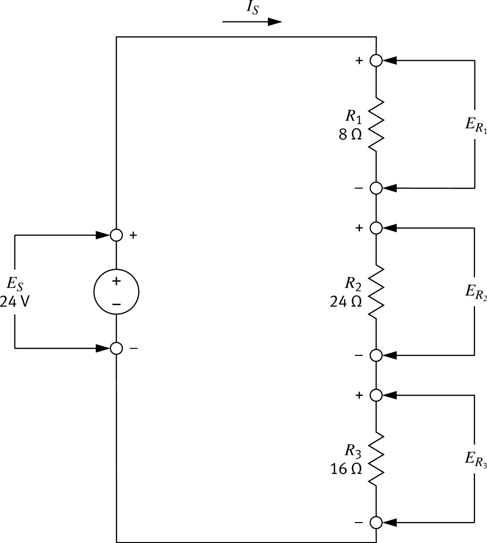
Three-Resistor Series Circuit
-
Given
ES = 24 V , R1 = 8 Ω , R2 = 24 Ω , R3 = 16 Ω -
Step 1 — Find Req
Req = R1 + R2 + R3 = 8 + 24 + 16 = 48 Ω -
Step 2 — Find IS
 IS = VReq IS = 24 V48 Ω = 0.50 A
 -
Step 3 — Voltage across each R
ER = IS × R ER1 = 0.50 × 8 = 4.00 V ER2 = 0.50 × 24 = 12.0 V ER3 = 0.50 × 16 = 8.00 V
Verify the Law Holds
The sum of all voltages in a
closed circuit loop equals 0 V
closed circuit loop equals 0 V
ES + ER1 + ER2 + ER3 = 0V
24.0V + (−4.00V) + (−12.0V) + (−8.00V) = 0V ✓
Kirchhoff's voltage law is verified — the algebraic sum of all voltages around any closed loop is always zero.
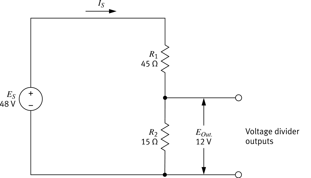
Two-Resistor Voltage Divider
- Output terminals connect across R2 (the lower resistor)
- Voltage across each resistor depends on its resistance ratio relative to Req
- With R1 = 45 Ω, R2 = 15 Ω, ES = 48 V:
Eout = ES × R2Req Eout = 48 V × 15 Ω45 Ω + 15 Ω = 12 V
- Swap R1 for 30 Ω → 16 V
- Swap R1 for 15 Ω → 24 V
Carefully selecting resistor values lets you tailor the output voltage for any application.
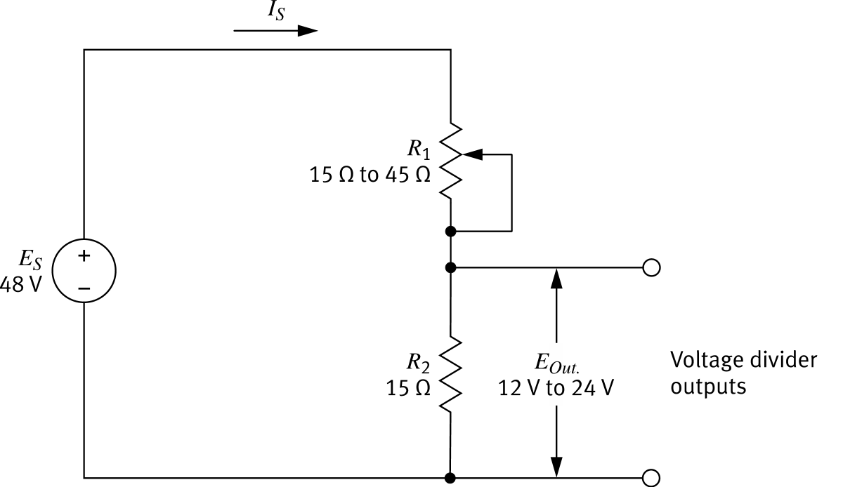
Rheostat & Resistor Divider
- R1 is a rheostat — its resistance can be dynamically adjusted
- R2 is a fixed resistor providing the output terminals
- The same divider can serve multiple purposes or supply a variable-voltage load
- With R2 = 15 Ω and ES = 48 V:
Eout = ES × R2Req R1 = 45 Ω → Eout = 48 V × 15 Ω60 Ω = 12 V R1 = 15 Ω → Eout = 48 V × 15 Ω30 Ω = 24 V
Potentiometer Voltage Divider
- A potentiometer's wiper physically divides it into two resistors with their Req equalling the total resistance
- Resistance values on each side depend on wiper position
- The higher the resistance across the output branch, the higher the output voltage
- With ES = 48 V, total pot = 60 Ω:
If we set R1, then R2 = 60 Ω − R1 Eout = ES × R2Req R1 = 0 Ω → Eout = 48 V × 60 Ω60 Ω = 48V R1 = 60 Ω → Eout = 48 V × 0 Ω60 Ω = 0V
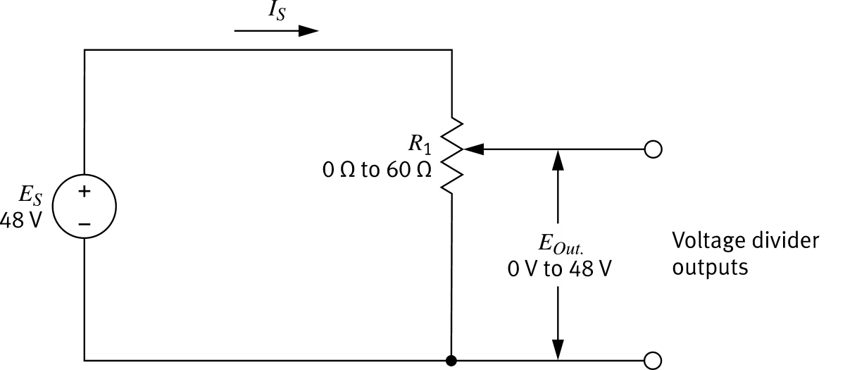
A potentiometer provides a continuously variable output across the full supply range.