What is Resistance?
Resistance is the opposition a material offers to the flow of current. The higher the resistance, the more it impedes electron flow.
Resistance is measured in ohms (Ω), named after German physicist and mathematician Georg Ohm, who discovered the relationship between voltage, current, and resistance.
Resistance is denoted by the letter R.
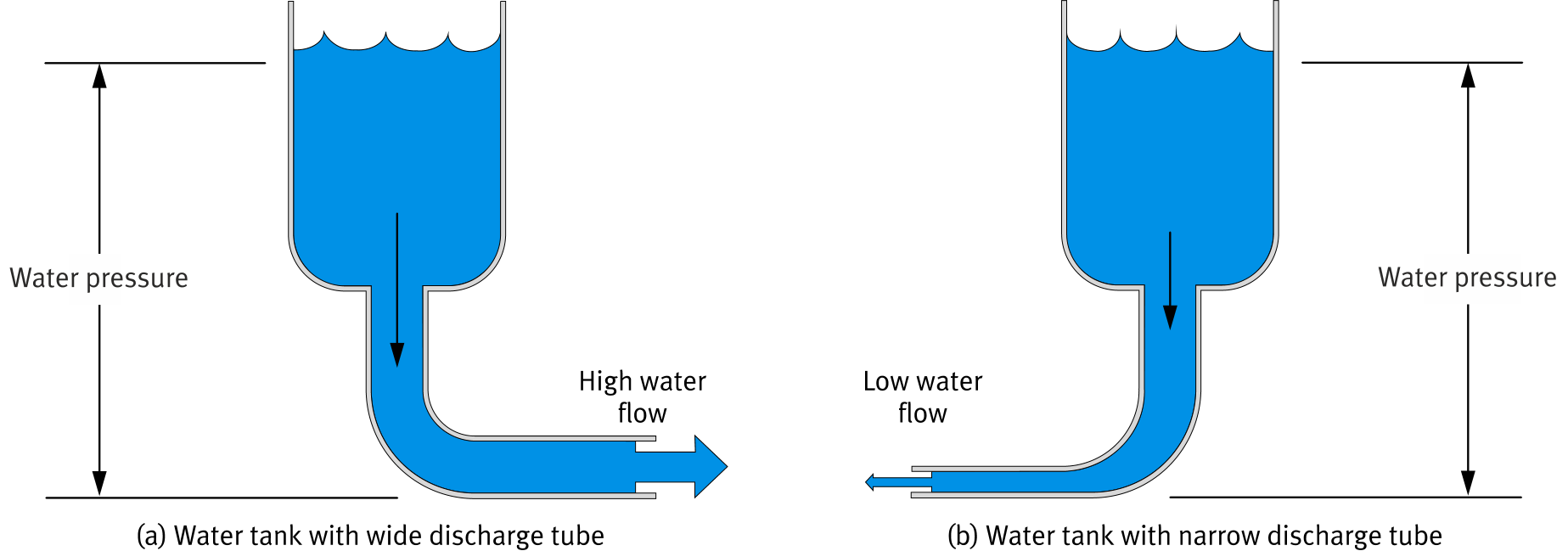
Water Tank Analogy
Resistance is analogous to the size of a water discharge tube. A wide tube (low resistance) lets more water flow; a narrow tube (high resistance) restricts flow.
Electrical charge ↔ water capacity
Voltage ↔ water pressure
Current ↔ water flow rate
Resistance ↔ tube diameter
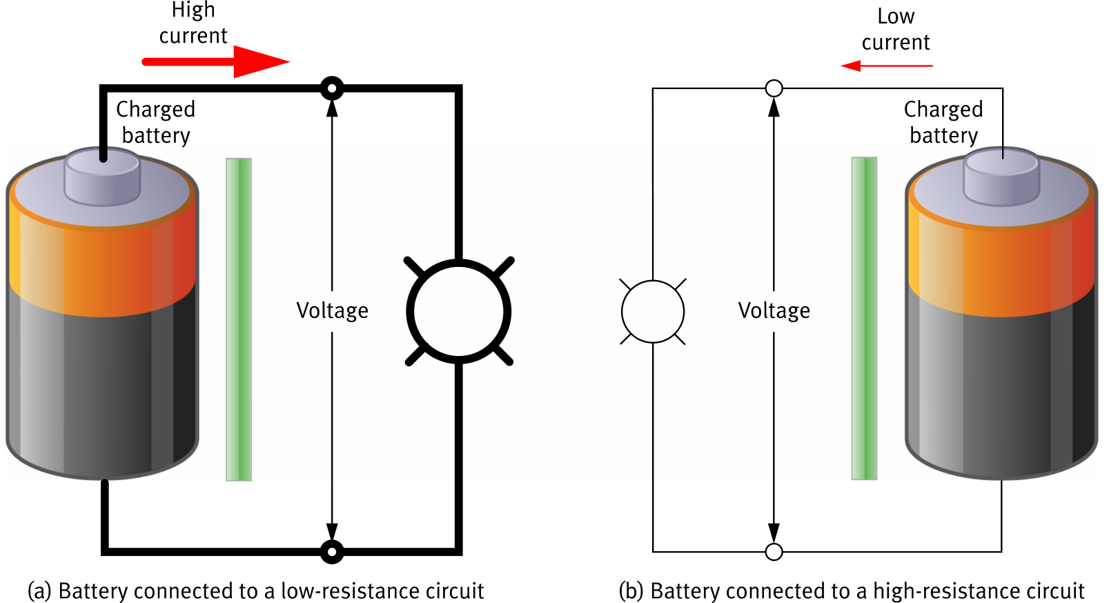
Resistance Affects Current
For the same voltage, a low-resistance circuit allows a high current to flow, while a high-resistance circuit restricts the current to a low value.
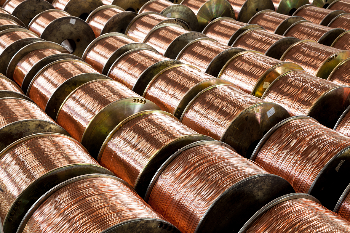
Two Categories of Materials
Low resistance: easily allow current to flow. Most metals are good conductors; copper is by far the most common. Used in electrical wires and transmission lines.
High resistance: impede or prevent current flow. Examples: glass, paper, Teflon, plastics, ceramic. Used in circuit boards, wire sleeves, and transmission line coatings.
Insulators in Practice
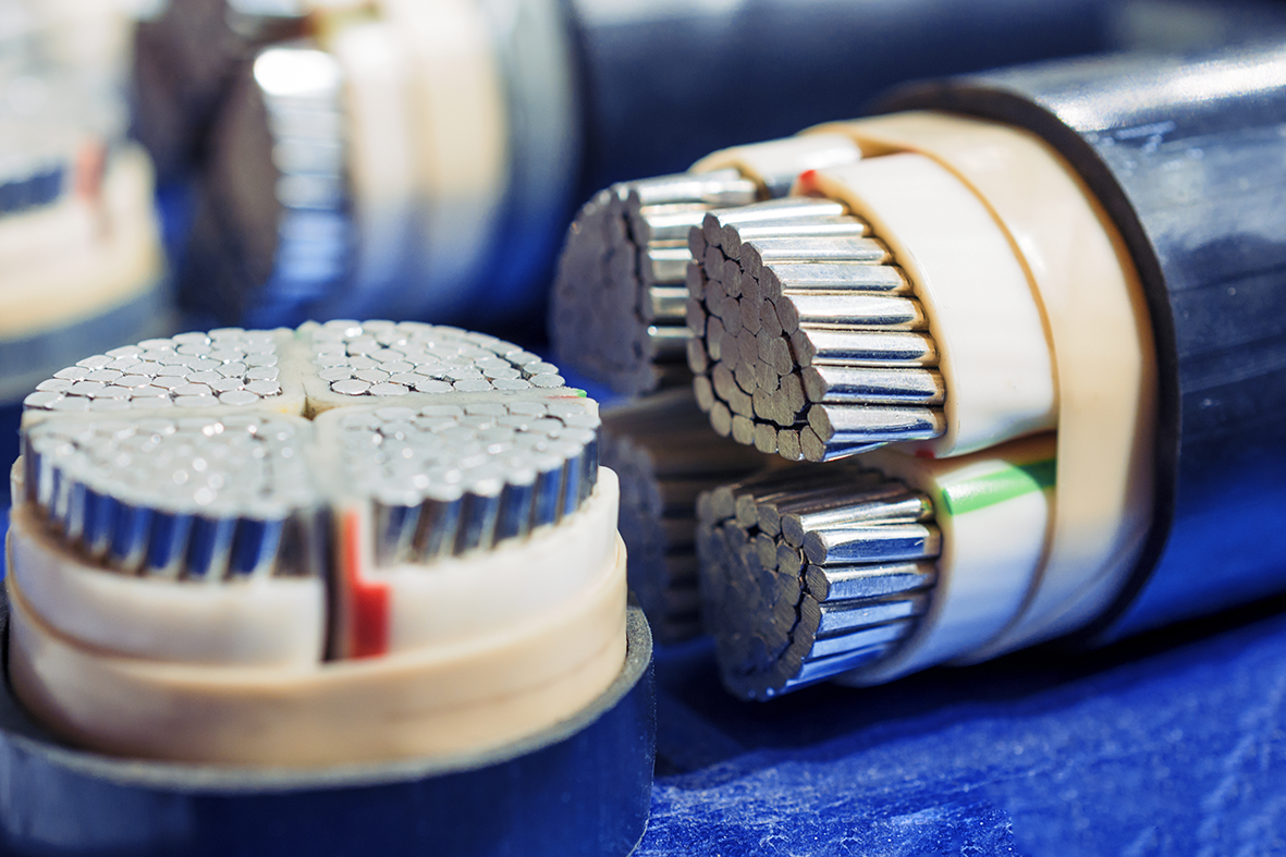
Electrical cables use insulating plastic or rubber sleeves around each conductor to prevent short circuits and protect against accidental contact.
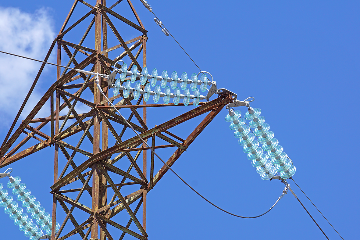
Porcelain or glass insulators on transmission towers keep high-voltage wires electrically isolated from the metal structure and the ground.
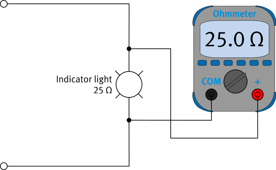
The Ohmmeter
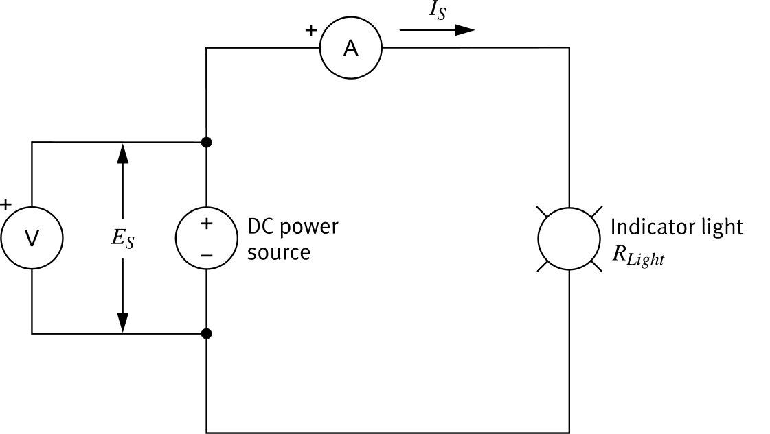
Resistance is measured using an ohmmeter. Like a voltmeter, it is connected in parallel across the two points where resistance is to be measured.
The ohmmeter applies a small voltage, measures the resulting current, then uses Ohm's law internally to display resistance.
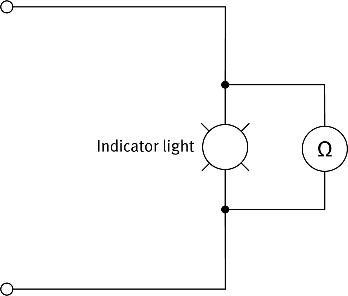
Ohmmeter Circuit Symbol
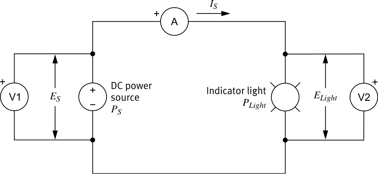
In circuit diagrams, the ohmmeter is represented by a circle containing the Ω symbol. This circuit shows the same indicator light measurement as the previous slide, this time using the schematic symbol.
| Component | Symbol |
|---|---|
| Ohmmeter |

|
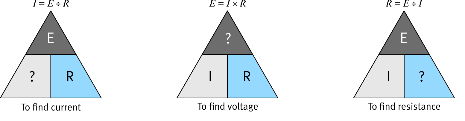
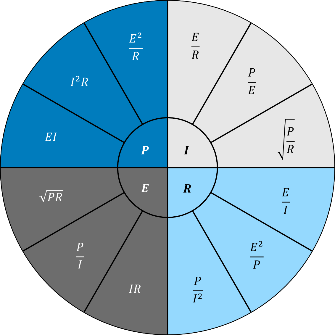
Reformulating the Equation
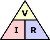
Ohm's law can be rearranged to solve for any of the three variables when the other two are known:
Worked Examples
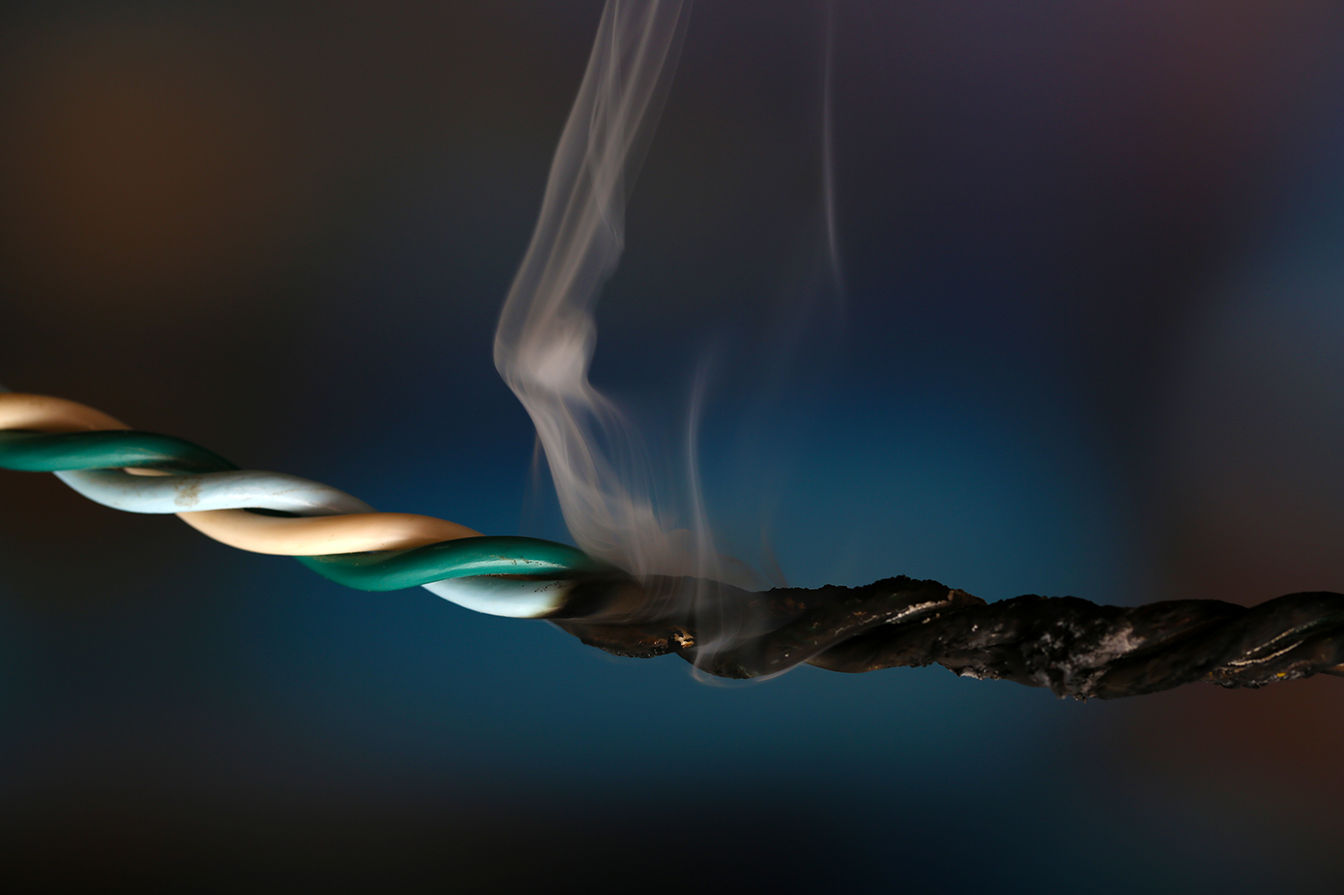
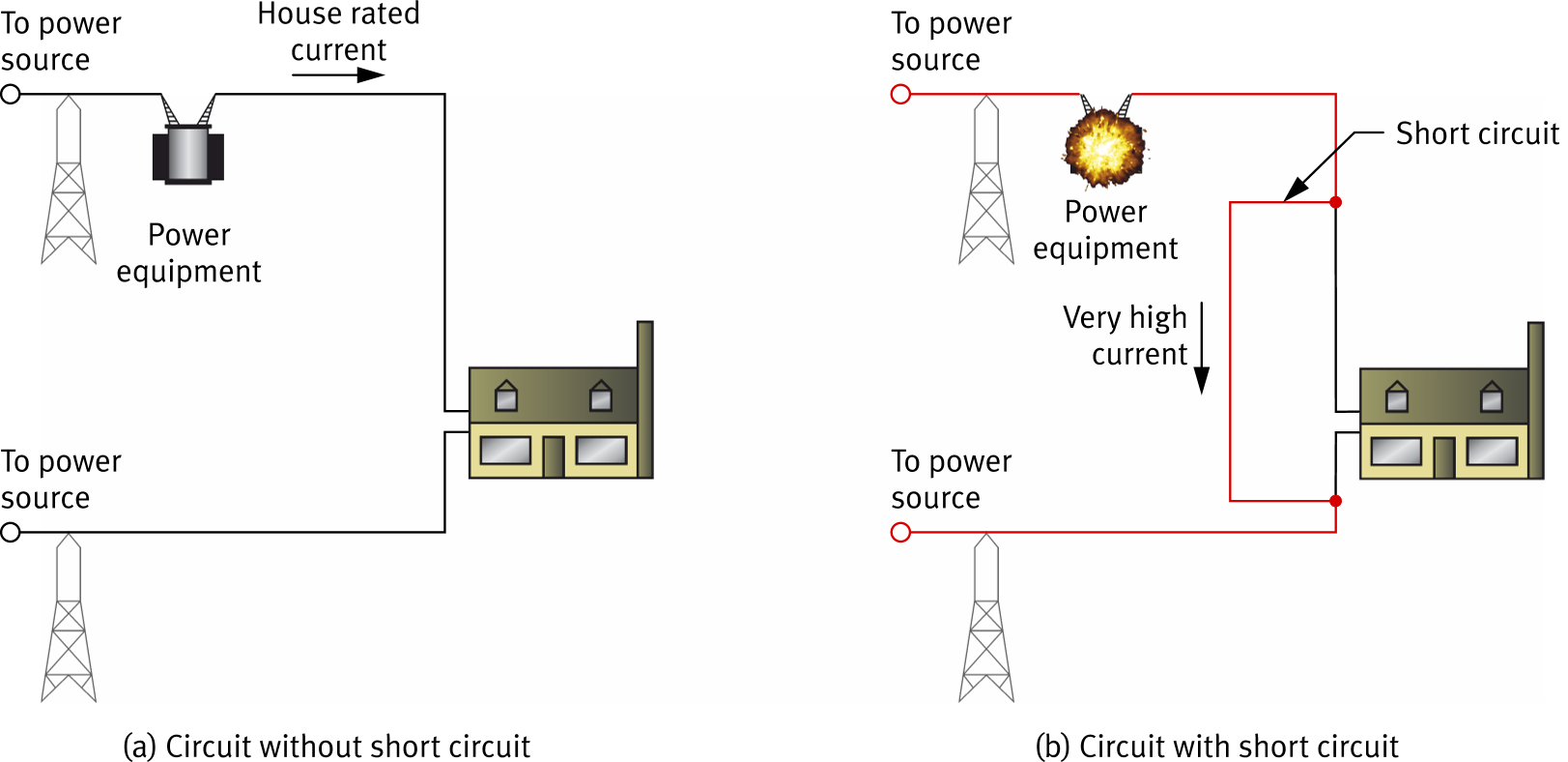
Short Circuits
A short circuit occurs when current flows along an unintended path with very low resistance, bypassing the load. This causes circuit resistance to approach 0 Ω.
Overheating wires and potentially damaging equipment.
Detect a short circuit by measuring resistance across the suspect points with an ohmmeter. A reading of 0 Ω or near 0 Ω confirms a short circuit.
Effects of a Short Circuit
In a normal circuit (a), current flows through the house load. The house resistance limits how much current flows.
When a short circuit occurs (b), current takes the low-resistance bypass path — skipping the house entirely. With almost no resistance, current spikes to a dangerously high level.
Open Circuits
An open circuit occurs when there is no path for current to flow; the circuit resistance is infinite.
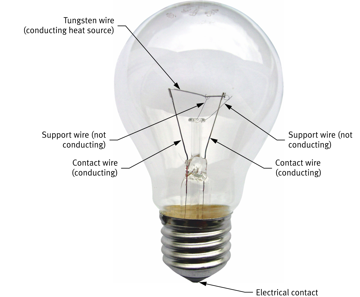
Open circuits can be intentional (an open switch) or accidental (faulty connections or a burned-out light bulb filament).
Continuity
Continuity between two points means current can flow; the resistance is anything but infinite. Testing for continuity is a key troubleshooting technique. Let's check for continuity between pairs of test points in this circuit.
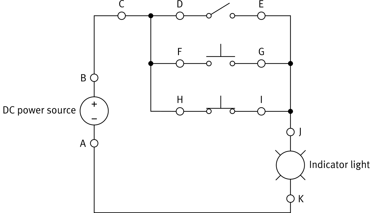
Complicated circuits can hide other paths.
What is Power?
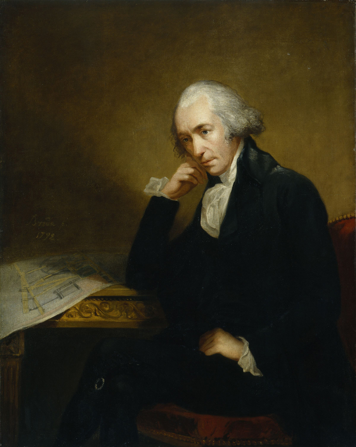
Power is the rate at which work is produced. Electrical power is measured in watts (W), named after Scottish engineer James Watt.
Power is denoted by the letter P. A power source supplies power to loads, which transform it:
- a light bulb converts it to heat & light
- a motor converts it to mechanical power
These transformations are never 100% efficient. Some power is always lost as heat.
The Power Equation
Power Calculations
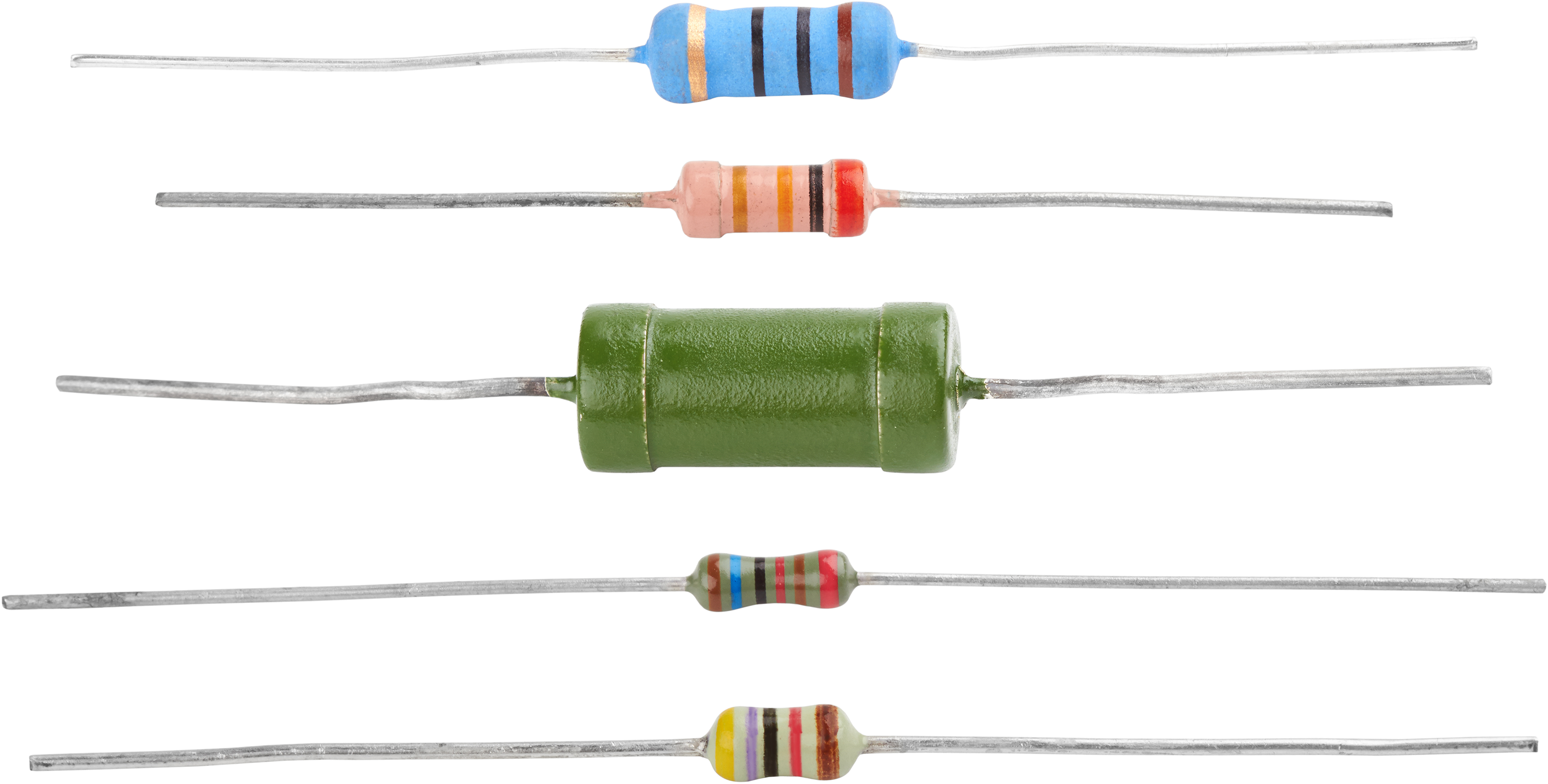
The Resistor
Resistors are designed to have a specific resistance value. They limit current and convert electrical power to heat.
| Component | Symbol |
|---|---|
| Resistor | 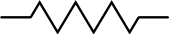 |
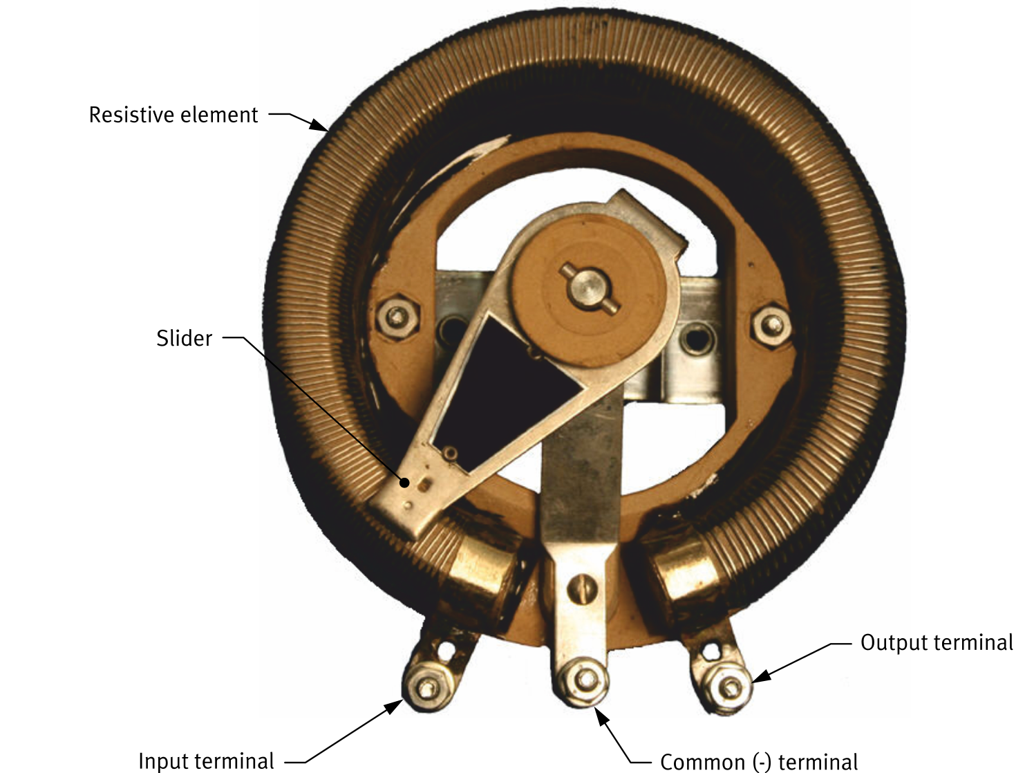
The Variable Resistor
A variable resistor has an adjustable resistance. It can control current or act as a voltage divider.
- Rheostat: two terminals, used for current control
- Potentiometer: three terminals, also allows voltage division
| Component | Symbol |
|---|---|
| Rheostat | 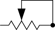 |
| Potentiometer | 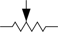 |
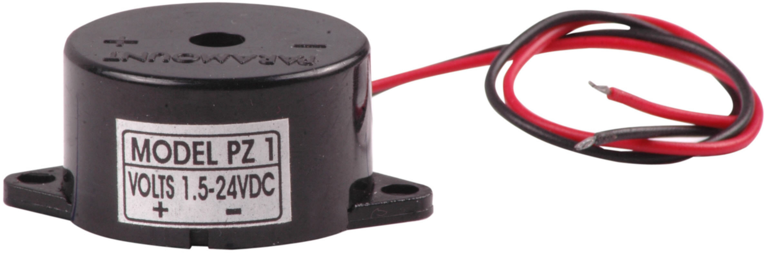
The Buzzer
An electromechanical buzzer emits an audible sound when powered. The training system uses a piezoelectric buzzer. Voltage applied to a piezoelectric material creates pressure oscillations that produce sound.
| Component | Symbol |
|---|---|
| Buzzer |  |
Key Takeaways
Opposition to current flow. Measured in ohms (Ω) with an ohmmeter connected in parallel.
Low-R materials (metals, copper) that allow current to flow easily.
High-R materials (glass, plastic, ceramic) that block current flow.
I = E/R · E = IR · R = E/I
Current ∝ voltage for constant R.
P = EI (watts). Combined with Ohm's law: P = E²/R or P = I²R.
Short circuit:
R ≈ 0, dangerously high I.
Open circuit:
R = ∞, I = 0 A.