Exercise 3

Series &
Parallel Circuits

Learning Outcome
01
Explain the principles of operation of series circuits and parallel circuits
Topics
  • What is a series circuit?
  • Series circuit examples: switches and loads
  • What is a parallel circuit?
  • Parallel circuit examples: independent control
  • Real-world application: car interior light
Series Circuits

What is a Series Circuit?

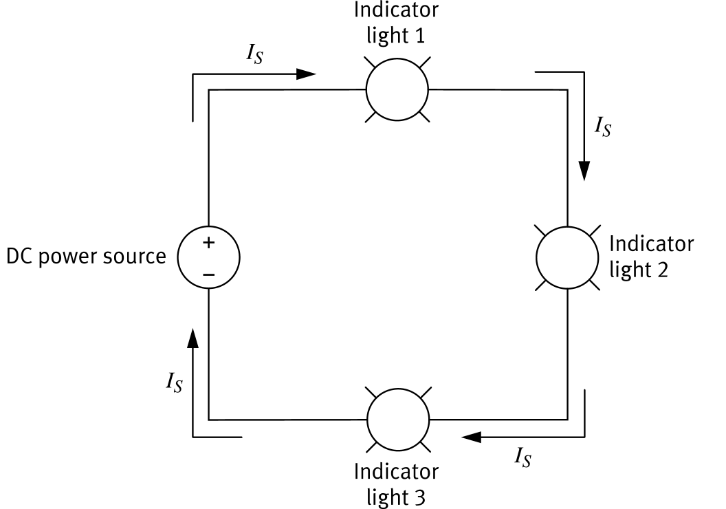
In a series circuit, components are connected along a single path. The same electrical current flows through every component in the circuit.

One path only: current has no alternative route through the circuit.
Same current everywhere: IS is identical through every component.
Break = total failure: removing any one component opens the circuit and stops current flow to all others.
Series circuit with three indicator lights showing I_S through each
Series Circuits

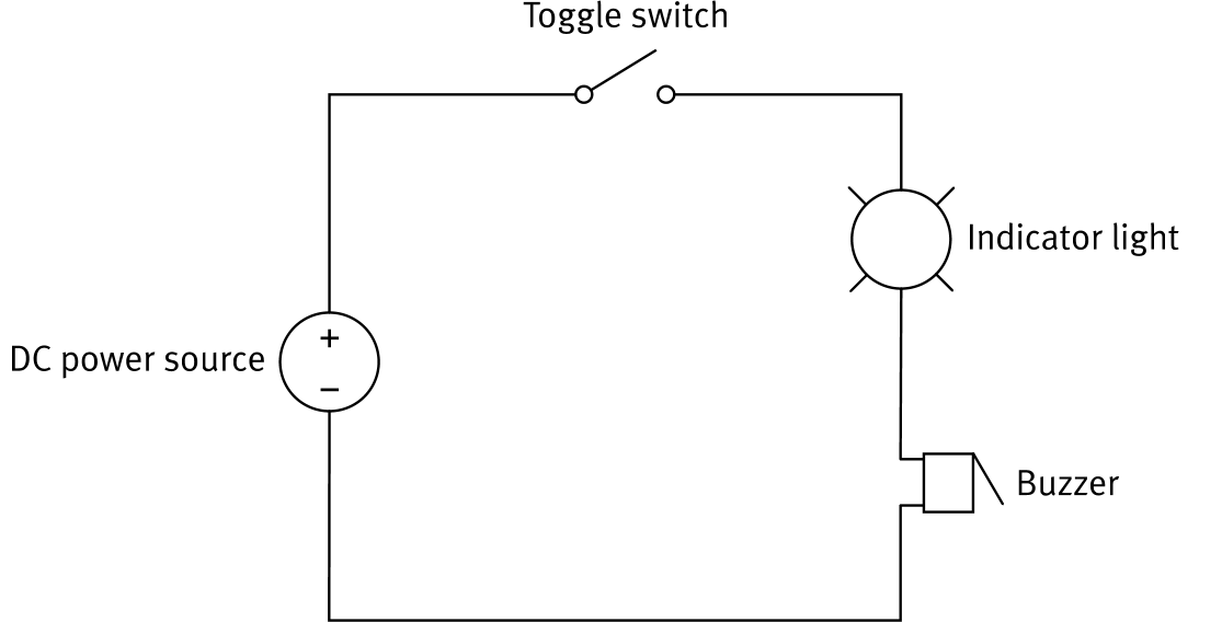
Switch Control in a Series Circuit

A switch placed in a series circuit controls all components at the same time.

Switch open: no current flows; the indicator light and the buzzer are both off.
Switch closed: current flows through both the indicator light and the buzzer simultaneously.
In a series circuit, independent control of individual components is not possible. One switch governs everything.
Series circuit with toggle switch controlling indicator light and buzzer
Series Circuits

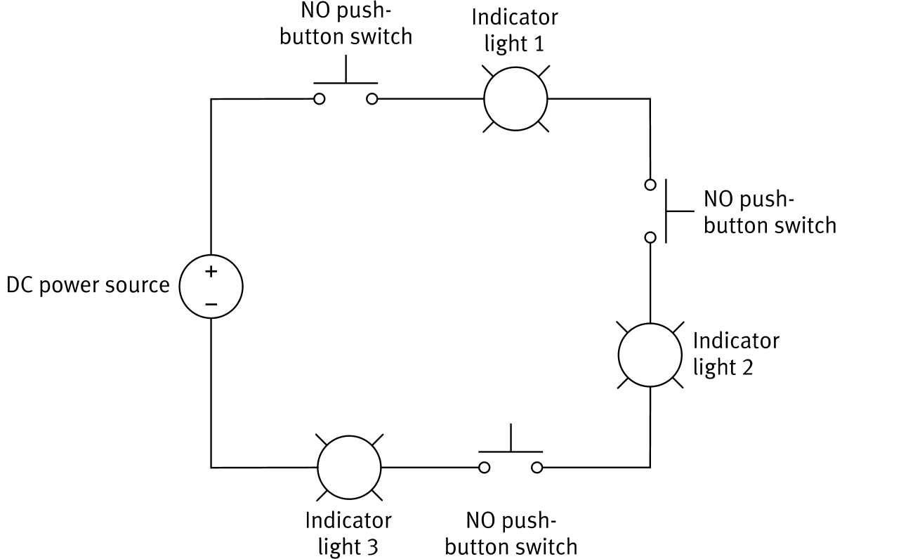
Series Circuit: Multiple Switches

Multiple NO push-button switches can be wired in series with several indicator lights. Since there is only one current path, the rule is strict:

All switches must be pressed simultaneously for current to flow and any light to turn on.

Releasing even one switch opens the circuit, stopping current and turning all lights off.

This is an AND logic gate in hardware: output is on only when input 1 AND input 2 AND input 3 are all active.
Series circuit with three NO push-button switches and three indicator lights
Parallel Circuits

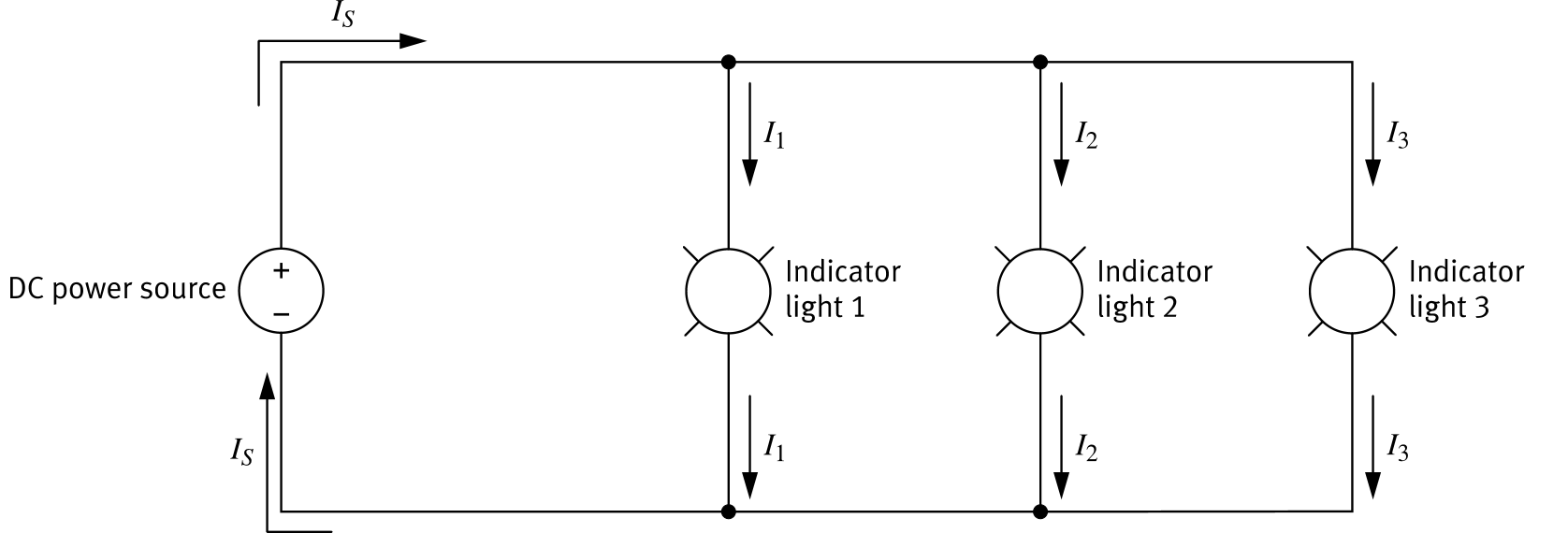
What is a Parallel Circuit?

In a parallel circuit, components are connected along more than one path. The source current IS splits into separate branch currents (I1, I2, I3) at each junction.

Multiple paths: current divides across branches; each component gets its own current.
IS = I1 + I2 + I3: branch currents recombine to equal the source current.
Fault tolerance: removing one component only breaks that branch. All other branches continue to operate normally.
Parallel circuit with three indicator lights showing I1, I2, I3 branch currents
Parallel Circuits

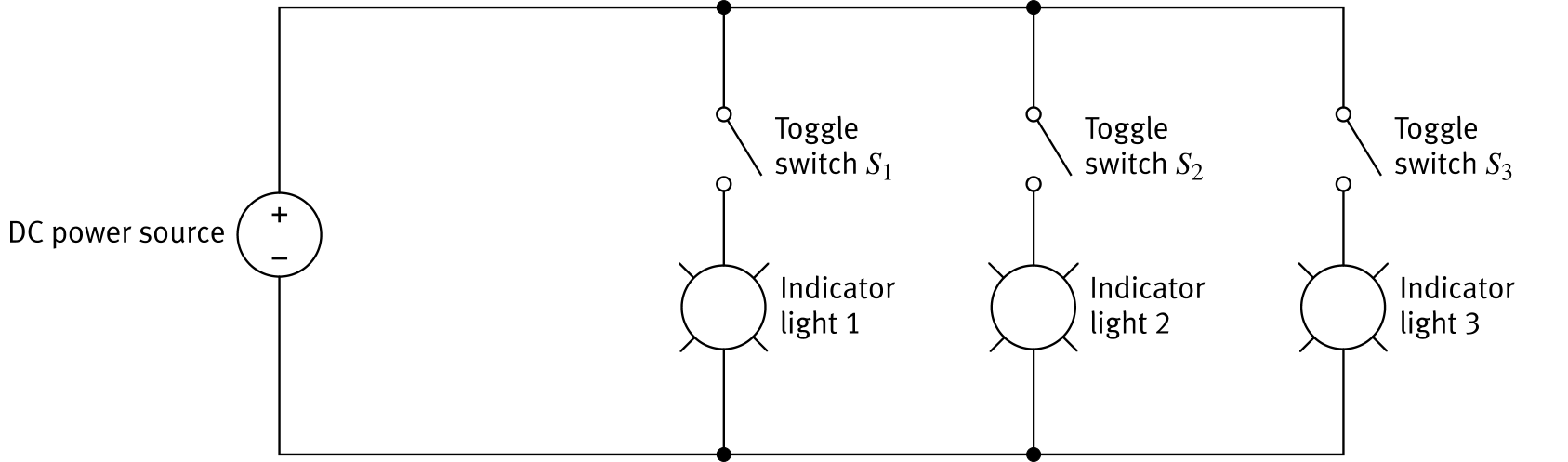
Independent Branch Control

Placing a toggle switch in each branch of a parallel circuit gives independent control over each component.

S1 open: light 1 is off. Lights 2 and 3 (with S2 and S3 closed) stay on.
Any combination: each switch controls only its own branch, with no effect on the others.
This is the fundamental advantage of parallel wiring over series: each branch can be switched on or off independently.
Parallel circuit with toggle switches S1 S2 S3 independently controlling three lights
Parallel Circuits

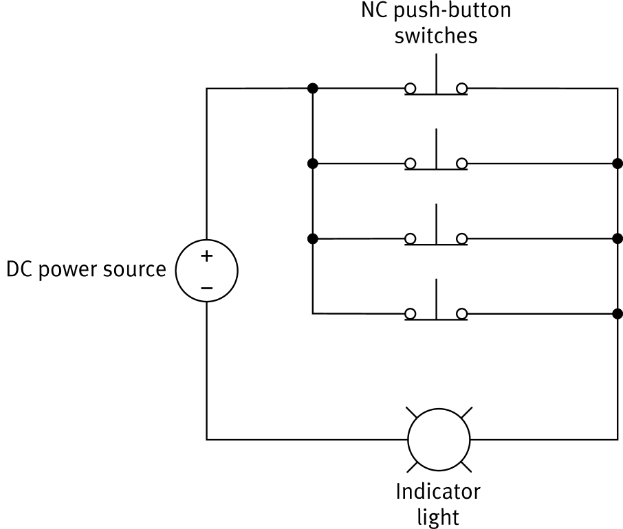
Real-World Example: Car Interior Light

A car interior light uses four NC push-button switches wired in parallel, one in each door hinge.

All doors closed: all four NC switches are pressed open; no current path exists; light is off.
Any door opens: its NC switch releases and closes; a current path forms; the light turns on.
Because the switches are in parallel, opening any single door is sufficient to complete the circuit. This is an OR logic gate: light on when door 1 OR door 2 OR door 3 OR door 4 is open.
Car interior light circuit with four parallel NC push-button switches
Exercise 3: Summary

Series vs. Parallel

Series Circuit Parallel Circuit
Current paths One single path Multiple paths (branches)
Current value Same through all components (IS) Divides across branches (I1 + I2 + … = IS)
Component removed Circuit opens; all components stop Only that branch stops; others continue
Switch control One switch controls everything Each branch switch controls only its branch
Switch logic AND (all switches must be closed) OR (any one switch can complete the circuit)