Get a partner and a breadboard.
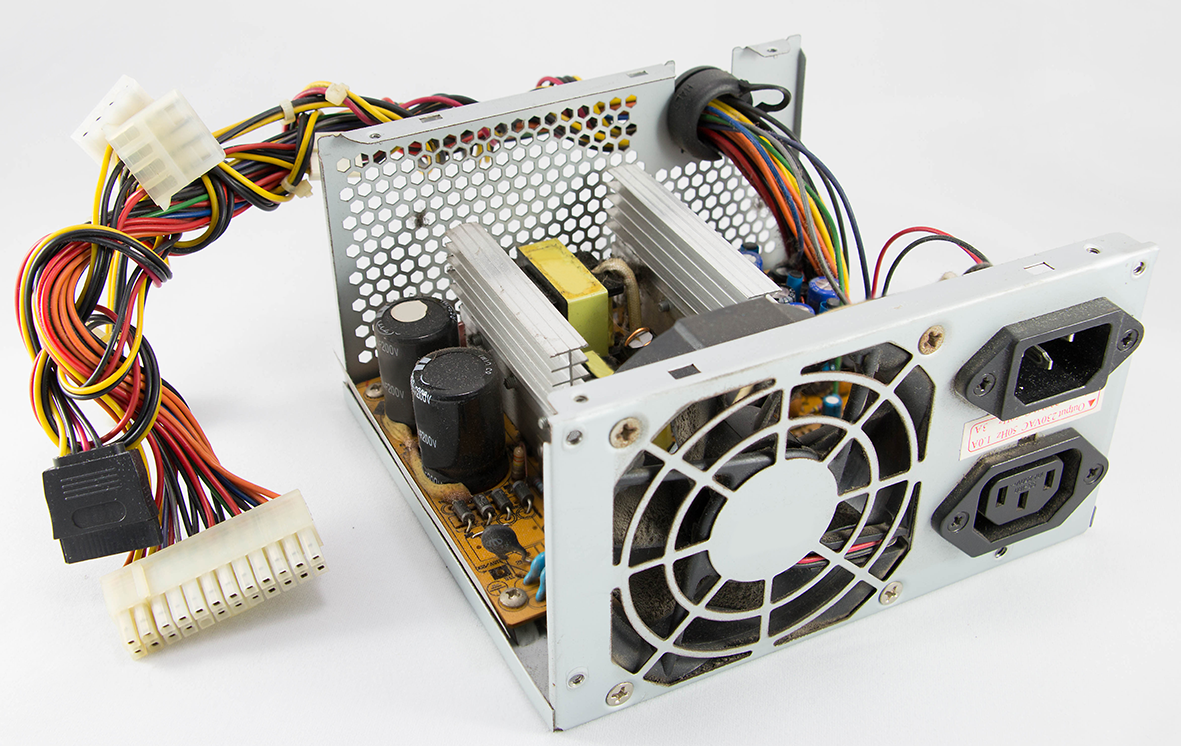
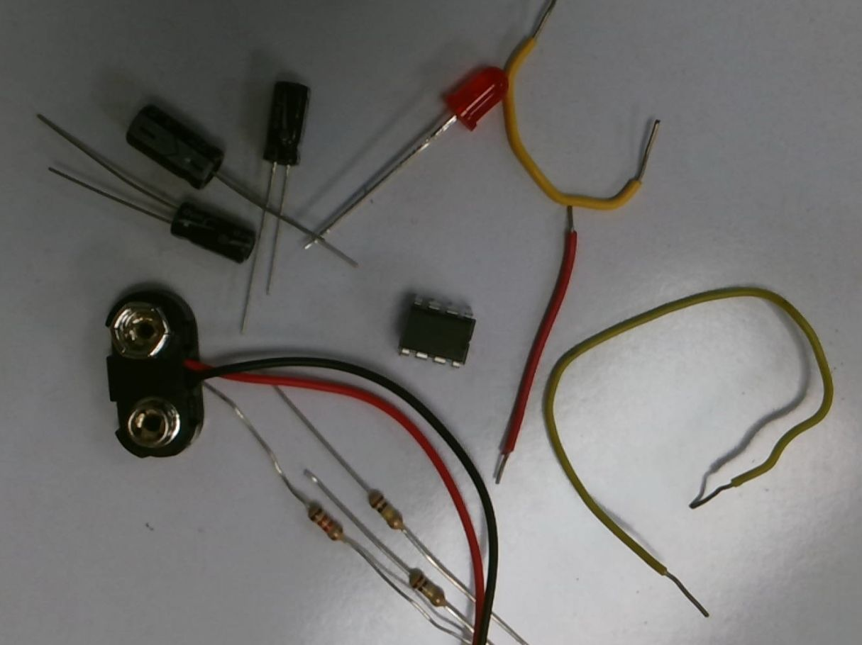
Gather your parts
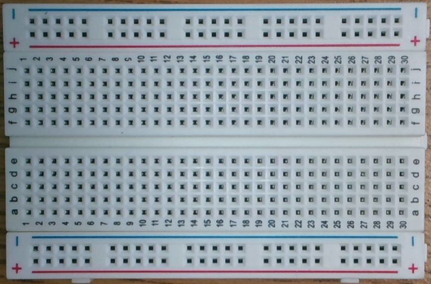
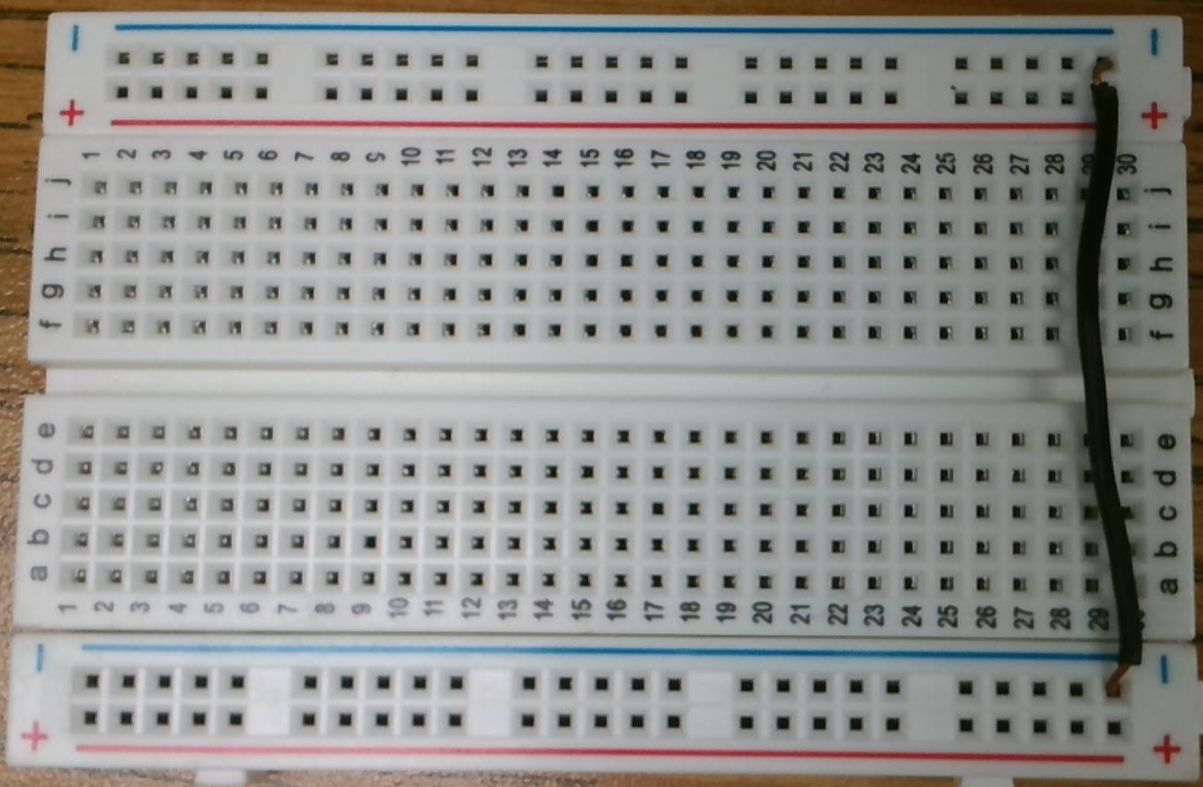
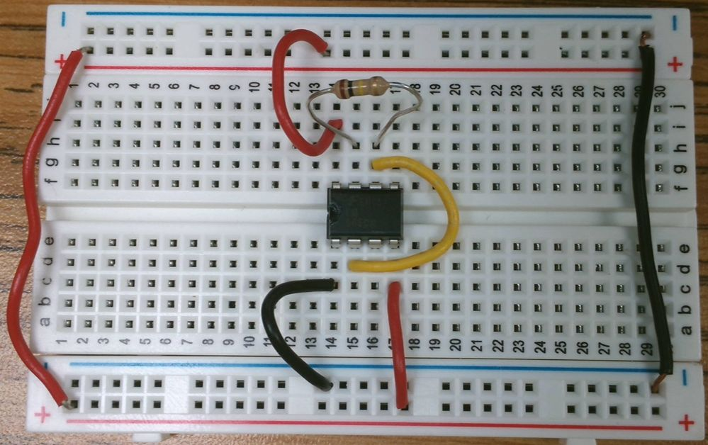
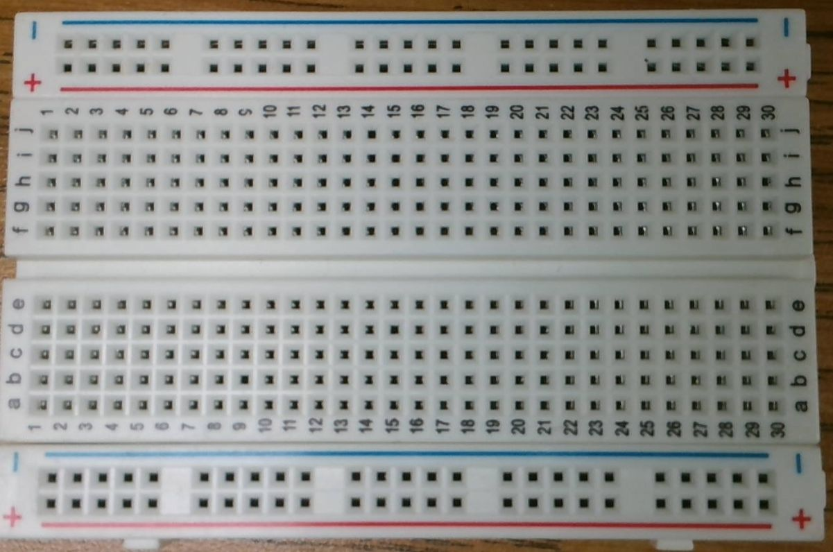 The Breadboard
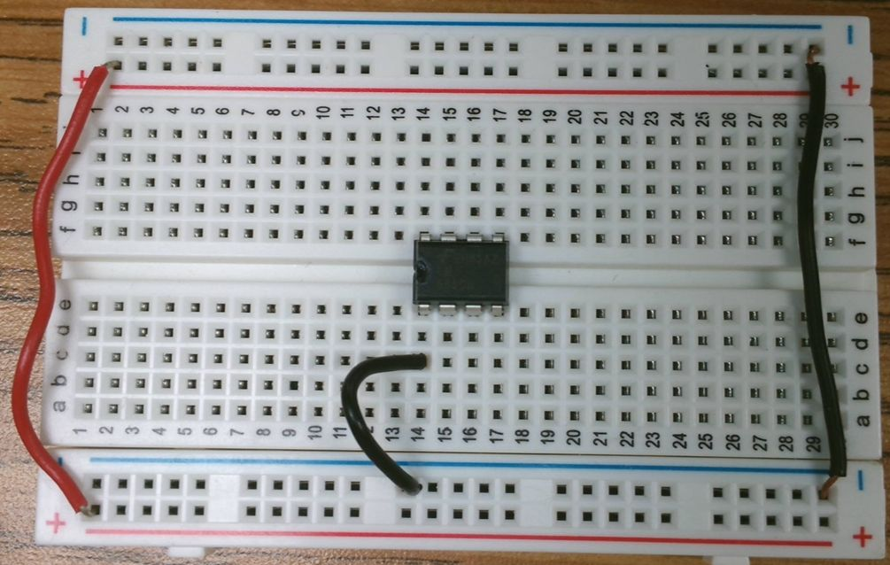
The power busses are long rails used to carry positive (red bus) and ground or negative (blue bus) across the board.
Each rail runs all the way across, but separate rails do not connect to each other even if they are the same color.

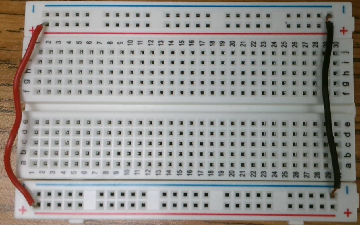
Use a wire to connect the two blue busses.
Use another wire to connect the two red busses.
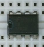
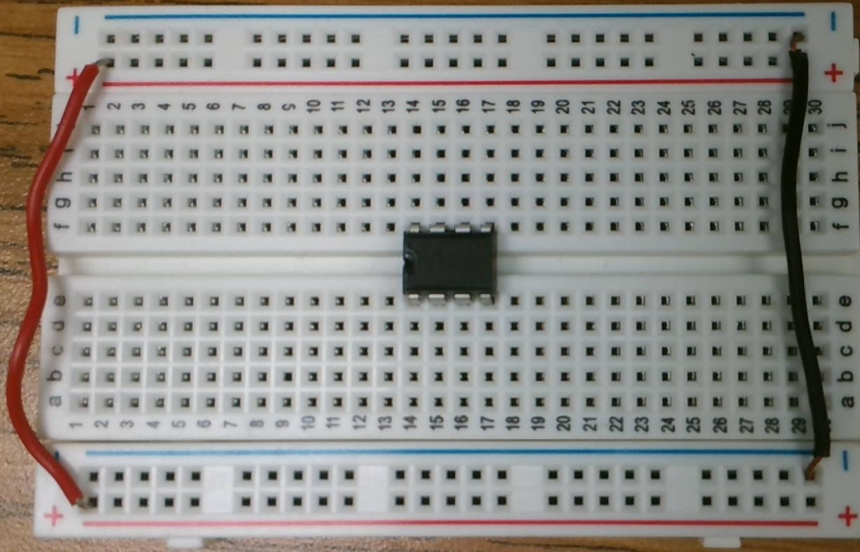
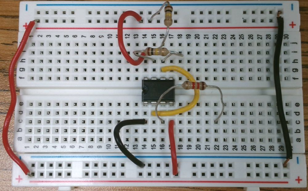
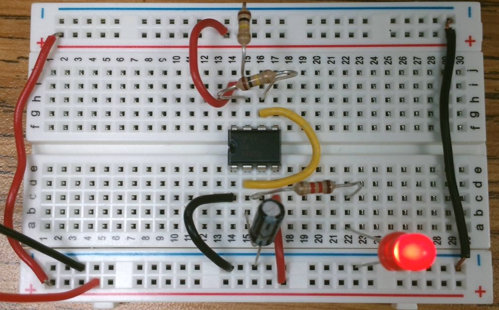
Place the IC. Pay attention to the notch or dot — it should be on the left side.

Integrated Circuits (ICs) have pins numbered starting at 1 and increasing counterclockwise.
The dot (or notch) identifies pin 1.
Pin 1 is the one closest to the dot, or the first counterclockwise from the notch.
The breadboard allows us to connect to the pins on the IC because each column of holes are connected, with a split down the middle.
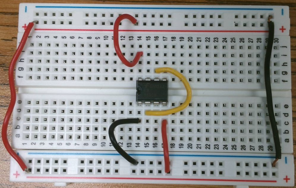
Let's connect the 555's power connections.
Start with connecting pin 1 to GROUND (blue bus).
Let's connect the 555's power connections.
Next, connect pin 8 to positive (red bus).
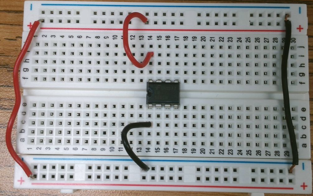
Pin 4 also needs to connect to the positive (red) bus.
While we are wiring things up, let's connect pin 2 to pin 6.

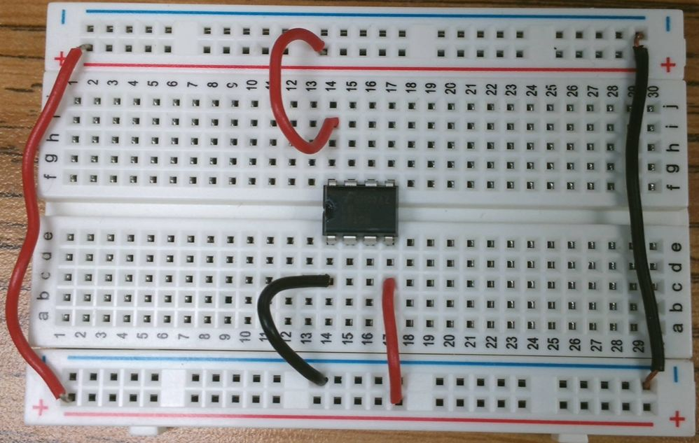
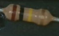
We have 3 resistors to add to the board. Two are 100KΩ or 100,000Ω with painted bands:
Brown, Black, Yellow, Gold

The first 100K resistor connects pin 6 and 7 of the 555.

The second 100K resistor connects pin 7 to positive voltage (red bus).

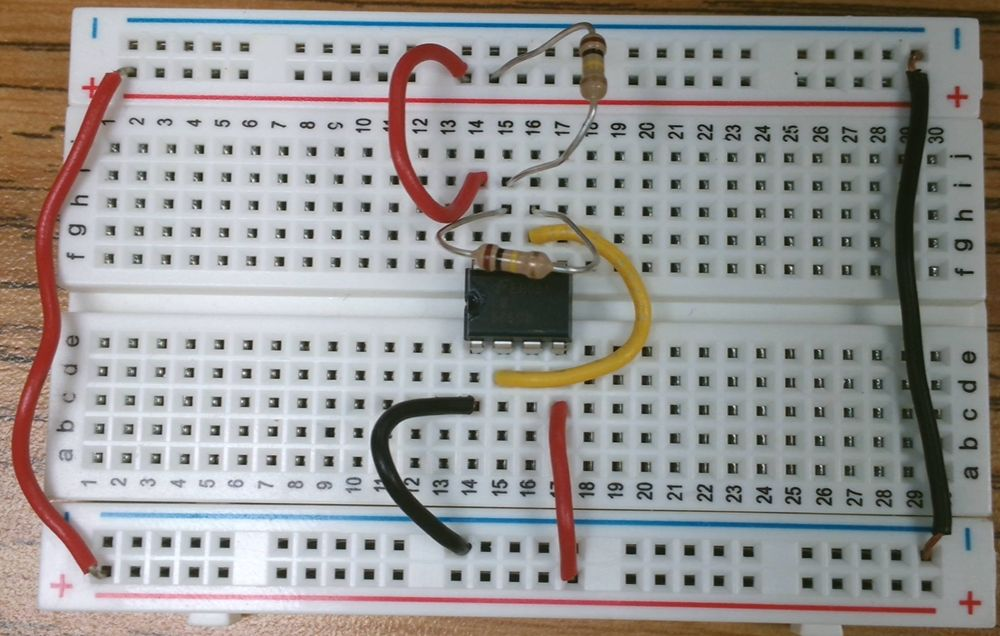
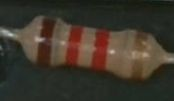
The third resistor, 1.2KΩ or 1,200Ω, is painted:
Brown, Red, Red, Gold
The 1.2KΩ resistor connects to pin 3 to an open column on the breadboard.

The 1.2KΩ resistor will connect our LED to the 555.

An LED is polarized. It only works in one direction.
You can tell which side is which by the length of the legs or the flat side at the bottom of the LED. The longer leg is positive, the flat side is negative.
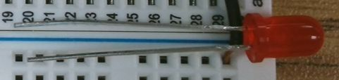
An LED is polarized. It only works in one direction.
The short leg or flat side goes to the blue bus. The long leg connects to the 1.2K resistor.

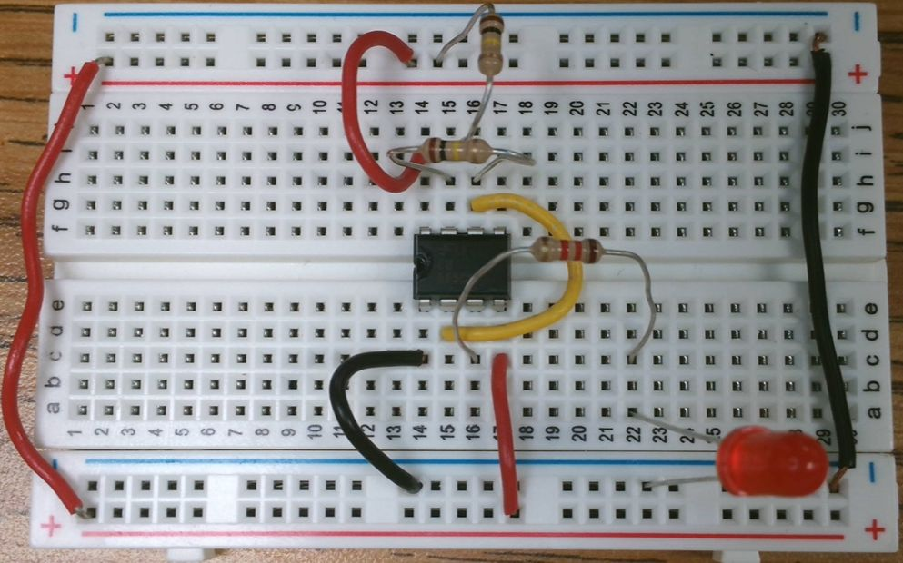
The capacitor we are using is also polarized. The side with the white stripe connects to negative (ground), the blue bus.
The other leg connects to pin 2 on the 555.
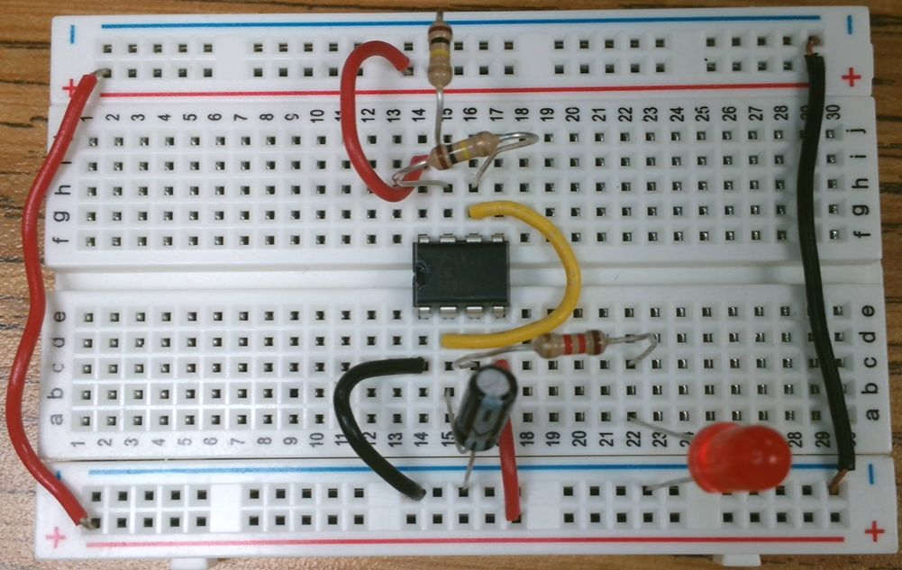
Next we need to connect the battery.
The Red wire connects to the Red bus.
The Black wire connects to the Blue bus.
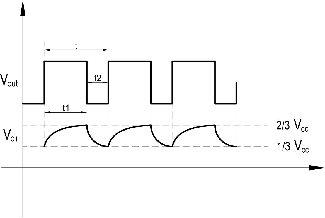
Time the Flashing
You should now have a flashing LED!
- Time how long it takes from the LED turning on until it turns on AGAIN
- Time how long the LED is on
What is a Circuit?
An electrical circuit is a connection of different elements forming a single network. The elements form a closed loop, allowing current to return to its origin.
Electrical circuits are composed of four basic components:
- 01A source of electrical power, such as a battery
- 02An electrical load that uses the power to produce work, such as a light bulb
- 03A continuous electrical path for electrons to flow with very little resistance
- 04A switch — not always essential, but often used to allow or prevent current flow
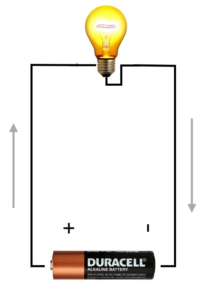
Conventional Current v. Electron Flow
Which direction does current move in a DC circuit?
In reality, electrons flow from the negative terminal to the positive terminal.
Safety Rules
Observe the following when using electrical equipment:
- 01 Always make sure the electrical power supply is disabled when connecting or disconnecting the power cord, leads, or components.
-
02
Never leave any electrical lead unconnected.
- Touching the unconnected end while power is enabled could give you an electric shock.
- A short circuit could occur if the unconnected end touches a conducting surface.
- 03 Double-check connections, especially polarized ones. Some components will break if current flows the wrong way.
-
04
Make sure contact terminals are free of dirt, oil, and water.
- Dirt and oil are insulators — they impair the connection between two components.
- Water is a conductor and might make an unwanted connection.

The AC/DC Training System is designed to teach the basic principles of dc and ac circuits to students with no prior knowledge of electricity.
It enables students to acquire both a theoretical and practical knowledge of the basic concepts of electricity.
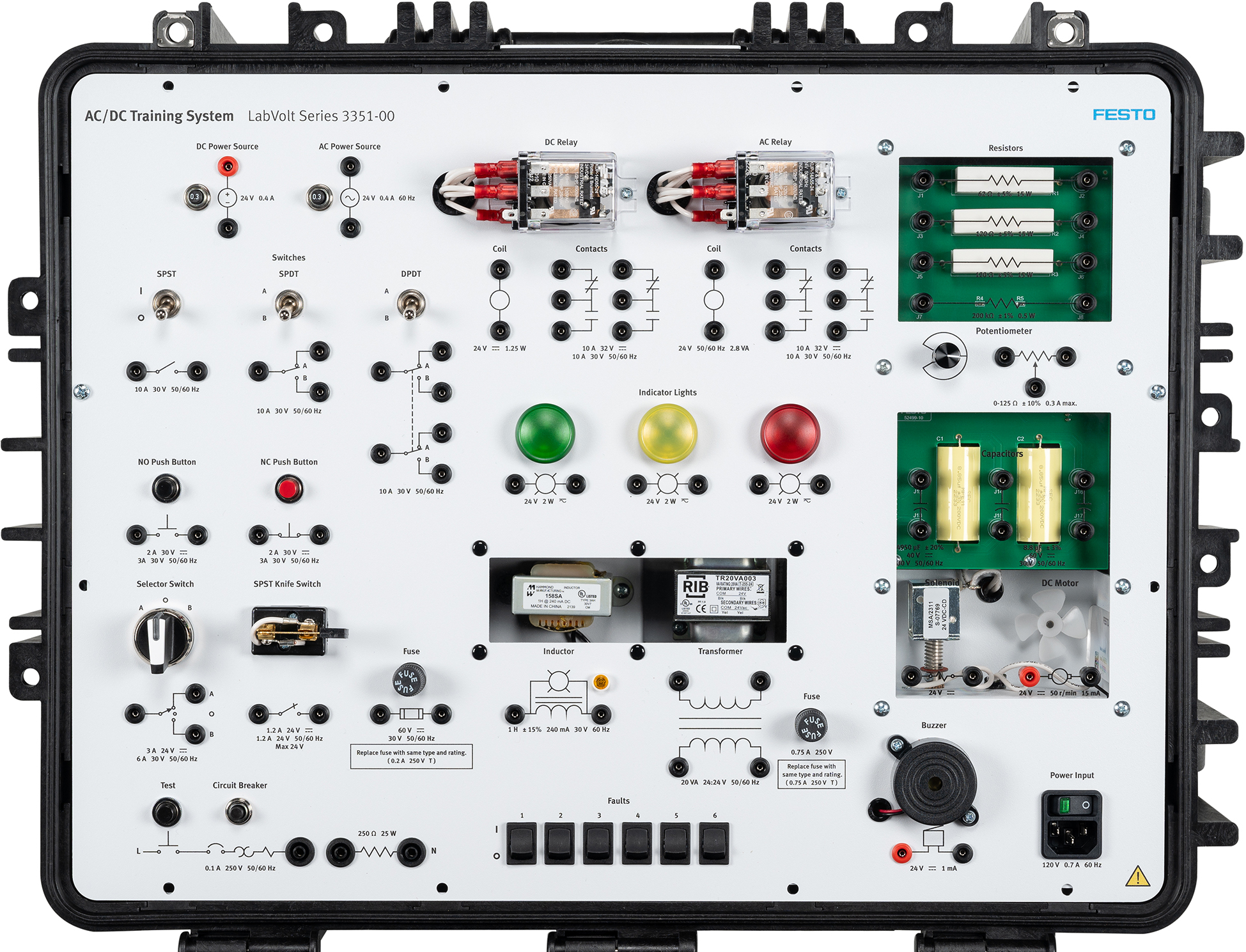
The DC Power Source
The dc power source is used in all procedures requiring dc power. It draws electricity from a standard electrical socket and supplies it to connected components.
Never turn it on unless the procedure states to do so. Doing otherwise could damage equipment or give you a shock.
- Voltage rating: 24 V
- Current rating: 1 A (circuit breaker trips at 1.2 A)
- Terminals are polarized — red (+) and black (−)
- Circuit breaker can be reset by pressing the button beside the source