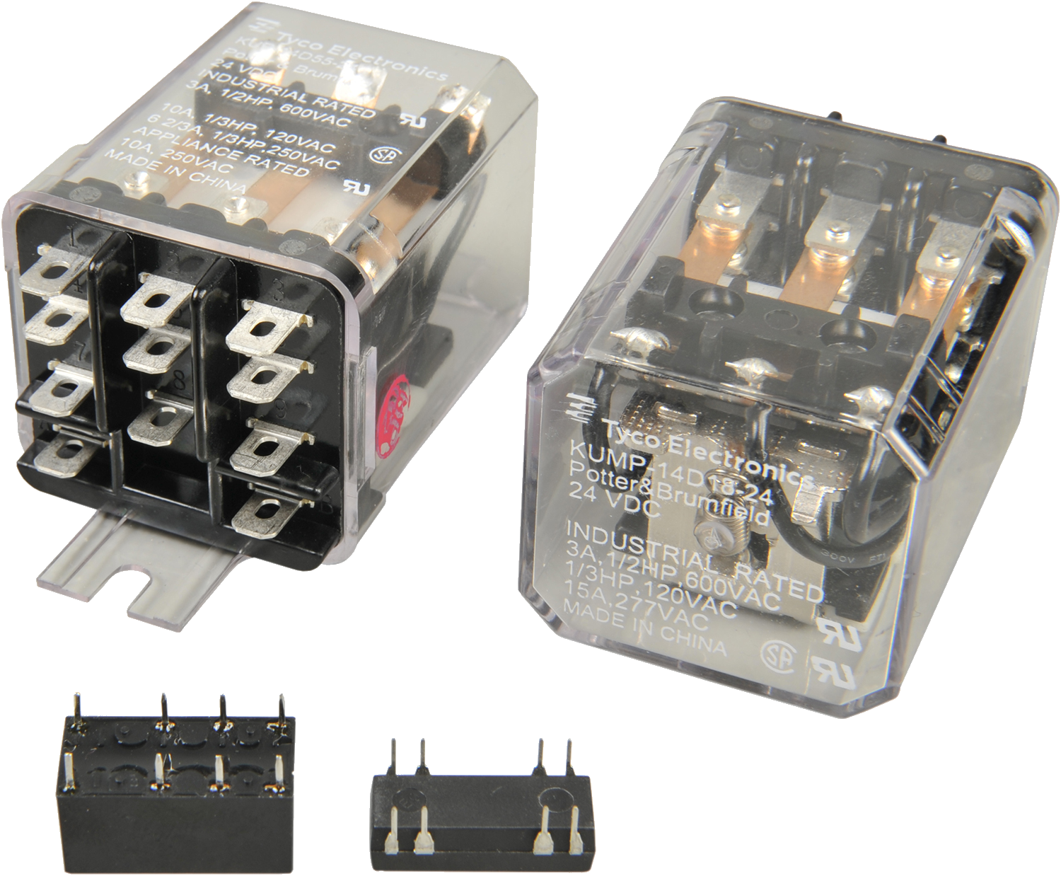
AR1  ·  DC Circuits Exercise 10  ·  Introduction

DC Relays

// Electromagnets  ·  Contacts  ·  NO & NC  ·  Applications

Overview

Learning Outcomes

  • Explain the principles of operation of DC relays
  • List applications of DC relays
  • Operate the AC/DC Training System DC relay

Topics Covered

01Introduction to DC relays
02Operation of DC relays
03Applications of DC relays
04Training system component: the DC relay
Introduction to DC Relays · Topic 01

What Is a Relay?

A relay is an electrically actuated switch which uses electromagnetism to open or close a circuit.

  • Consists of an electromagnet (a coil of wire wound around an iron core) and one or more sets of contacts
  • Each set of contacts acts exactly as a switch, opening or closing the circuit as required
  • Key difference: switches are mechanically actuated; relays are electrically actuated
  • This property makes relays more desirable than switches in certain applications
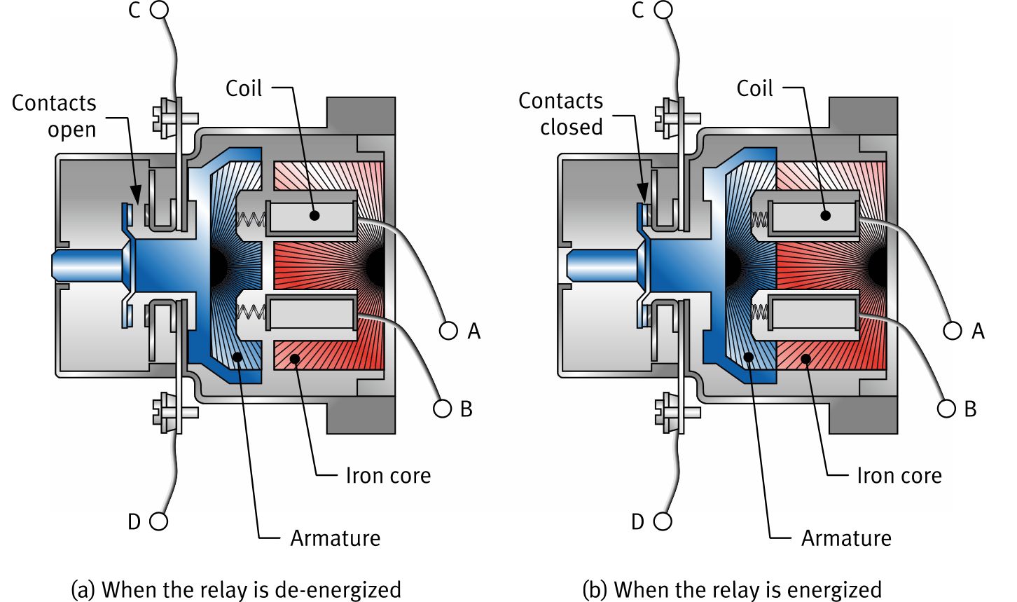
Different types of DC relay, large industrial relay and small PCB relay
Operation of DC Relays · Topic 02

How a Relay Works

a
De-energized

No current flows in the coil → no magnetic field → armature released → contacts open

The relay acts like a toggle switch in its open state. Any circuit connected to terminals C and D is open.

b
Energized

Current flows through terminals A and B → magnetic field → armature attracted → contacts close

The relay acts like a toggle switch in its closed state. Any circuit connected to terminals C and D is closed.

Key Definition
A coil with current flow is energized. A coil without current flow is de-energized.
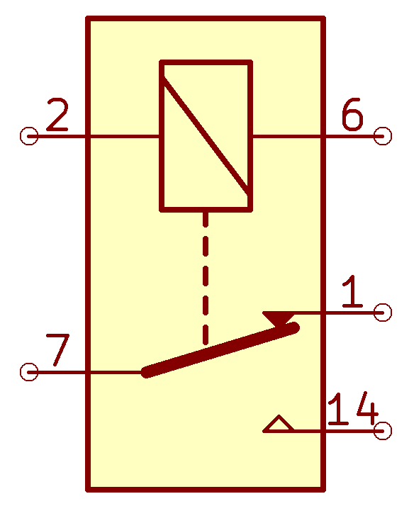
Cross-section of a relay: (a) de-energized, contacts open, (b) energized, contacts closed
Operation of DC Relays · Topic 02 · Circuit Symbols

Circuit Symbols

In circuit diagrams, the coil and contacts of a relay can be drawn as separate symbols. They are part of the same component but belong to independent circuits.

Component Symbol
Relay — Coil CR
Relay — NO contact
Relay — NC contact
Schematic symbol of a DC relay showing coil and contact

Two Separate Circuits

The coil and contacts form independent circuits. This is the key advantage of a relay.

Coil Circuit
Low-voltage control
Energizes or de-energizes the relay
Contact Circuit
Switched load
Controlled by the coil, not connected to it
Why It Matters
A low-voltage control signal at A/B can safely switch a high-voltage, high-current load at C/D.
Operation of DC Relays · Topic 02 · Example Circuit

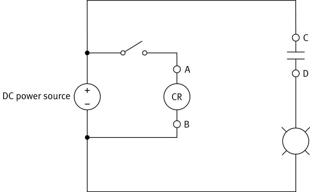
Example: Indicator Light Circuit

  • The switch and relay coil (CR) form the control circuit.
  • The indicator light is connected in series with the relay contacts at terminals C and D
  • Switch open:
    coil de-energized → contacts open → light off
  • Switch closed:
    coil energized → contacts close → light turns on
Key Takeaway
The indicator light's operation is controlled by allowing or preventing current flow in the relay coil. The two circuits never touch.
Circuit diagram: indicator light controlled by a DC relay with switch and CR coil
Applications of DC Relays · Topic 03

Applications of DC Relays

Relays are electrically actuated switches that are used wherever a control signal must operate a load circuit at a safe distance or power level.

High-Power Switching
The human operator interacts only with the low-power coil circuit, never the high-power load. Relays used in high-power applications are often called contactors. Examples: heavy-duty motor starters.
Logic Control Circuits
Relays can implement logic by connecting coils and contacts in series, parallel, or mixed configurations. Used instead of PLCs when the process logic is simple enough.
Protection (Protective Relays)
Certain relays are designed to open a circuit when a fault condition occurs. An overvoltage relay energizes as soon as the coil voltage reaches a threshold. Its contacts then open to interrupt the faulty circuit.
Training System Component · Topic 04

The DC Relay in the AC/DC Training System

The training system DC relay has a coil and two independent sets of contacts. Each has both an NO and NC terminal.

Component Specifications
Coil voltage: 24 V DC
Max contact voltage: 32 V
Max contact current: 10 A
Contact sets: 2 independent
Do Not Exceed Ratings
Applying more than 32 V or more than 10 A across the relay contacts could damage the relay and prevent normal operation.

Contact Set Details

Independent circuits — each contact set controls a completely separate circuit
NO terminal — open when de-energized, closes when the 24 V coil is energized
NC terminal — closed when de-energized, opens when the 24 V coil is energized
Simultaneous use — both contact sets operate at the same time when the coil is energized
Example
When the coil is energized, the circuit on the NC contact opens while the circuit on the NO contact closes at the same time.